
Circuit and method for extracting amplitude and phase information in a resonant system

a resonant system and amplitude information technology, applied in the direction of electric variable regulation, process and machine control, instruments, etc., can solve the problems of consuming a large amount of power, fast analog to digital converters (adcs), and usually being costly

Active Publication Date: 2014-10-30
TEXAS INSTR INC
View PDF2 Cites 20 Cited by
  • Summary
  • Abstract
  • Description
  • Claims
  • Application Information

AI Technical Summary

Benefits of technology

The invention provides a better way to optimize the operation of an inductive wireless power transmitter-receiver system. This method reduces power consumption and electromagnetic interference by controlling the amount of dead-time to achieve zero-voltage-switching (ZVS) of the switches. This results in a simpler, more flexible, and cost-effective system than previous methods.

Problems solved by technology

Sampling the phase and amplitude of a state variable may require very fast analog to digital converters (ADCs), which usually are costly and consume a large amount of power.
For example, various remote receivers or other loads may frequently become connected and / or disconnected, and that causes the system operating point (or points) to vary considerably and therefore become non-optimal.

Method used


Image

  • Circuit and method for extracting amplitude and phase information in a resonant system
  • Circuit and method for extracting amplitude and phase information in a resonant system
  • Circuit and method for extracting amplitude and phase information in a resonant system

Examples


Embodiment Construction

[0050]Difficulties encountered due to the presence of parasitic circuit elements at high frequencies (e.g., roughly 6 MHZ) can result in reduced performance of conventional sensing circuits in wireless power transfer systems because of the effects of such parasitics on measurement of the system operating points. An alternate sensing method has been found for measuring the system operating point for achieving the objective of providing a relatively simple, flexible, and cost-effective design of an inductive power transfer system.

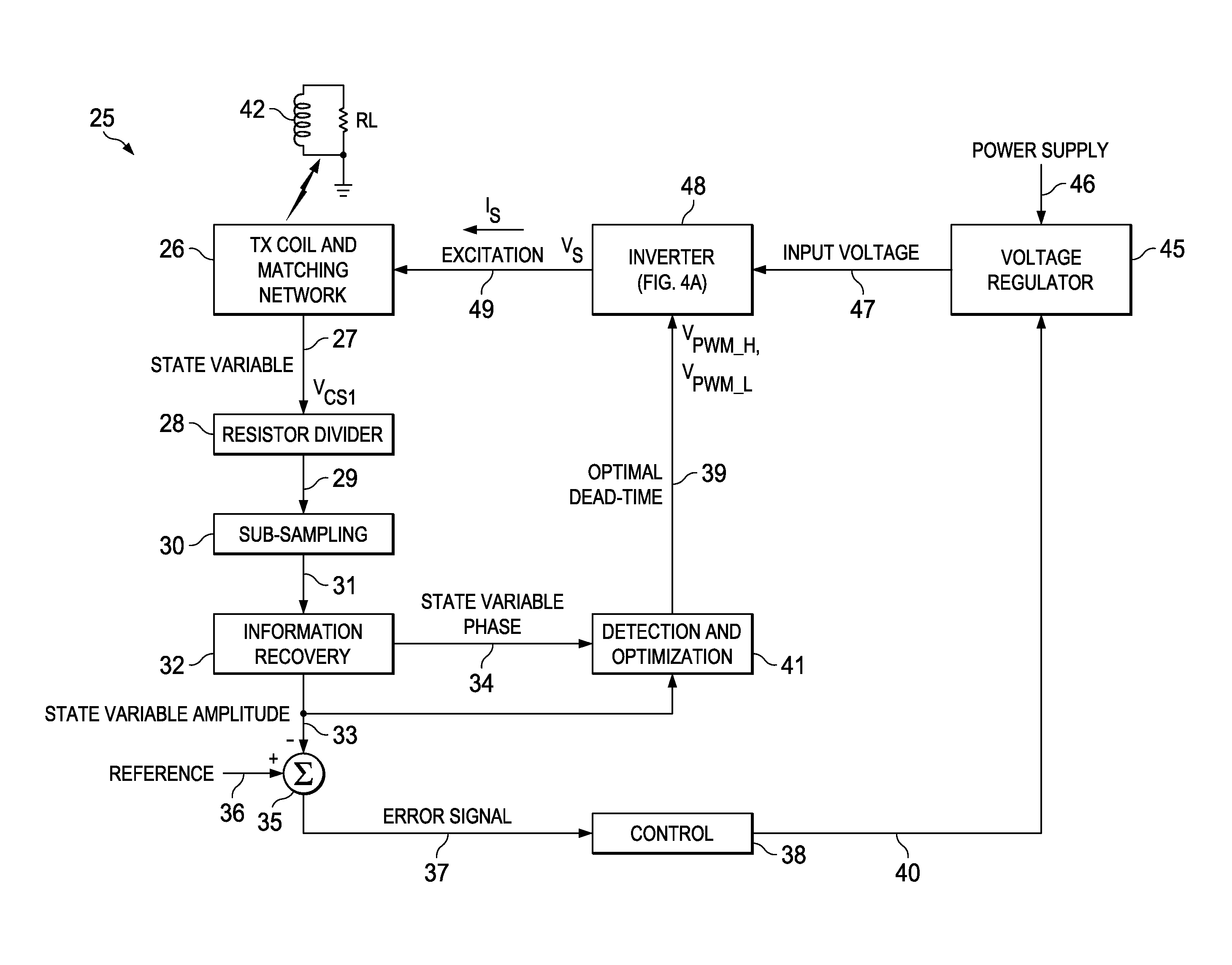
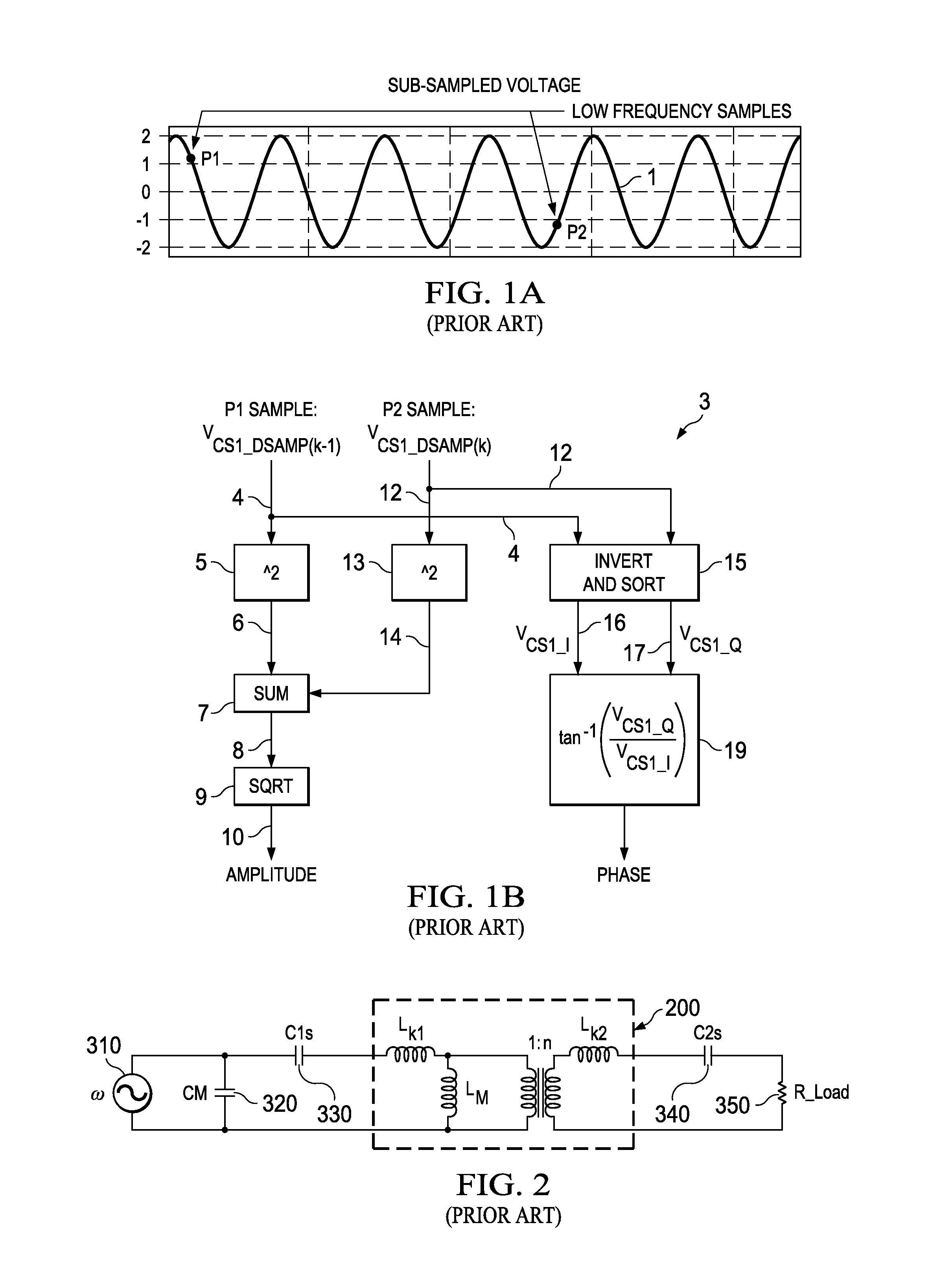
[0051]To overcome the previously mentioned difficulties, a wireless power transfer system is disclosed wherein a power transmitter excites a transmitter coil at a high frequency. It may be desirable / necessary to detect both the amplitude and phase of the current in the transmitter inductor coil in order to determine the operating point of the system. In accordance with the present invention, known sub-sampling techniques are utilized to extract such amplitude...


PUM


Abstract

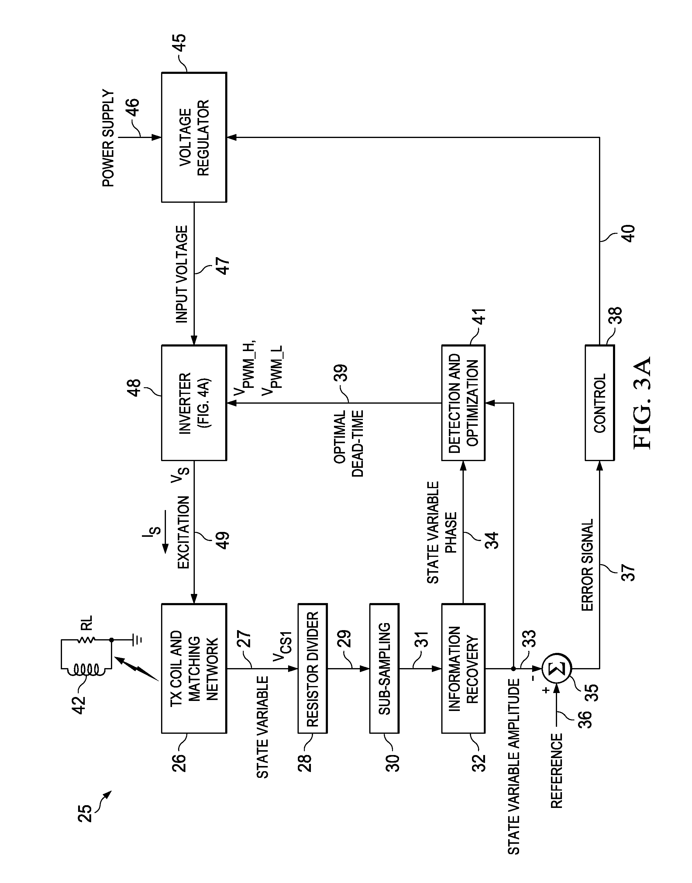
A resonant power transfer system includes resonant circuitry (26) including an inductor coil (59) and a resonant capacitor (51) coupled to a first terminal (27) of the inductor coil, wherein the inductor coil and the resonant capacitor resonate to produce an excitation signal (IS) and a state variable signal (VCS1). Sub-sampling circuitry (30) samples first and second points of the state variable signal at a rate which is substantially less than the RF frequency of the state variable signal. Information recovery circuitry (32) produces a state variable parameter signal representing a parameter (A) of the state variable signal from information in the first and second sampled points. Control circuitry (38) produces a first control signal in response to the state variable parameter signal. Detection and optimization circuitry (41) produces a second control signal in response to the state variable parameter signal. Voltage regulation circuitry (45) produces a regulated supply voltage in response to the first control signal. Switching inverter circuitry produces the excitation signal in response to the regulated supply voltage and the second control signal.

Description

CROSS REFERENCE TO RELATED APPLICATION[0001]This application claims the benefit of prior filed co-pending U.S. provisional application Ser. No. 61 / 816,408 filed Apr. 26, 2013, entitled “Method to Extract Amplifute [Amplitude] and Phase Information in a Resonant System to Optimize System Operation”, by Gianpaolo Lisi, Gerard Socci, Ali Djabbari, Rajaram Subramonian, and Kosha Mahmodieh, and incorporated herein by reference.BACKGROUND OF THE INVENTION[0002]The present invention relates generally to optimizing operation of a resonant system for inductive power transfer between a transmitter and receiver system, or a “wireless power transfer system”, and more particularly to optimizing parameters of “state variables” that affect an “operating point” of the resonant system. The invention also relates to performing the optimization in a way that results in the system being simpler, more flexible, and more cost-effective than is the case in prior systems.[0003]A resonant inductive power tr...

Claims


Application Information

Patent Timeline
IPC IPC(8): G05F1/12H01F38/14
CPCH01F38/14G05F1/12H02M7/53803Y02B70/10
Inventor LISI, GIANPAOLOSOCCI, GERARDDJABBARI, ALISUBRAMONIAN, RAJARAMMAHMODIEH, KOSHA
Owner TEXAS INSTR INC
Learn More