Oscillation actuator

a technology of oscillating actuator and actuator, which is applied in the direction of generator/motor, mechanical apparatus, machine/engine, etc., can solve the problems of increasing the wear of sliding parts, difficulty in increasing the torque, and cracks or defects in layers, so as to improve the durability and increase the torque of oscillating actuator.

Inactive Publication Date: 2014-10-30
TOYOTA IND CORP
View PDF2 Cites 2 Cited by
  • Summary
  • Abstract
  • Description
  • Claims
  • Application Information

AI Technical Summary

Benefits of technology

[0005]As described above, since the oscillation actuator uses the frictional force acting between the moving element and the oscillator to drive the moving element, then in order to improve durability, it is necessary to reduce the wear of the sliding portions between the moving element and the oscillator by lubricating the sliding portions. On the other hand, in order to raise the drive torque of the moving element, it is necessary to raise the pressure contact force between the moving element and the oscillator to make the frictional force between the moving element and the oscillator greater. And the increase in the frictional force brings in an increase in the wear of the sliding portions. More specifically, in an oscillation actuator, improving durability and increasing the torque are in the relationship of trade-off.
[0007]This invention was devised in order to resolve the above problems, the object thereof being to provide an oscillation actuator that achieves both improved durability and increased torque.
[0024]According to this invention, it is possible to achieve both improved durability and increased torque in an oscillation actuator.

Problems solved by technology

And the increase in the frictional force brings in an increase in the wear of the sliding portions.
However, these layers provided on the sliding portions between the moving element and the oscillator, cracks or defects may occur in the layers if the pressure contact force between the moving element and the oscillator is too high.
In other words, when using a solid lubricant to lubricate the sliding portion between the moving element and the oscillator, it is difficult to increase the torque while guaranteeing durability.
Because the upper limit value of the pressure contact force between the moving element and the oscillator is limited by the hardness or the adhesiveness of the layers.

Method used


Image

  • Oscillation actuator
  • Oscillation actuator
  • Oscillation actuator

Examples


first embodiment

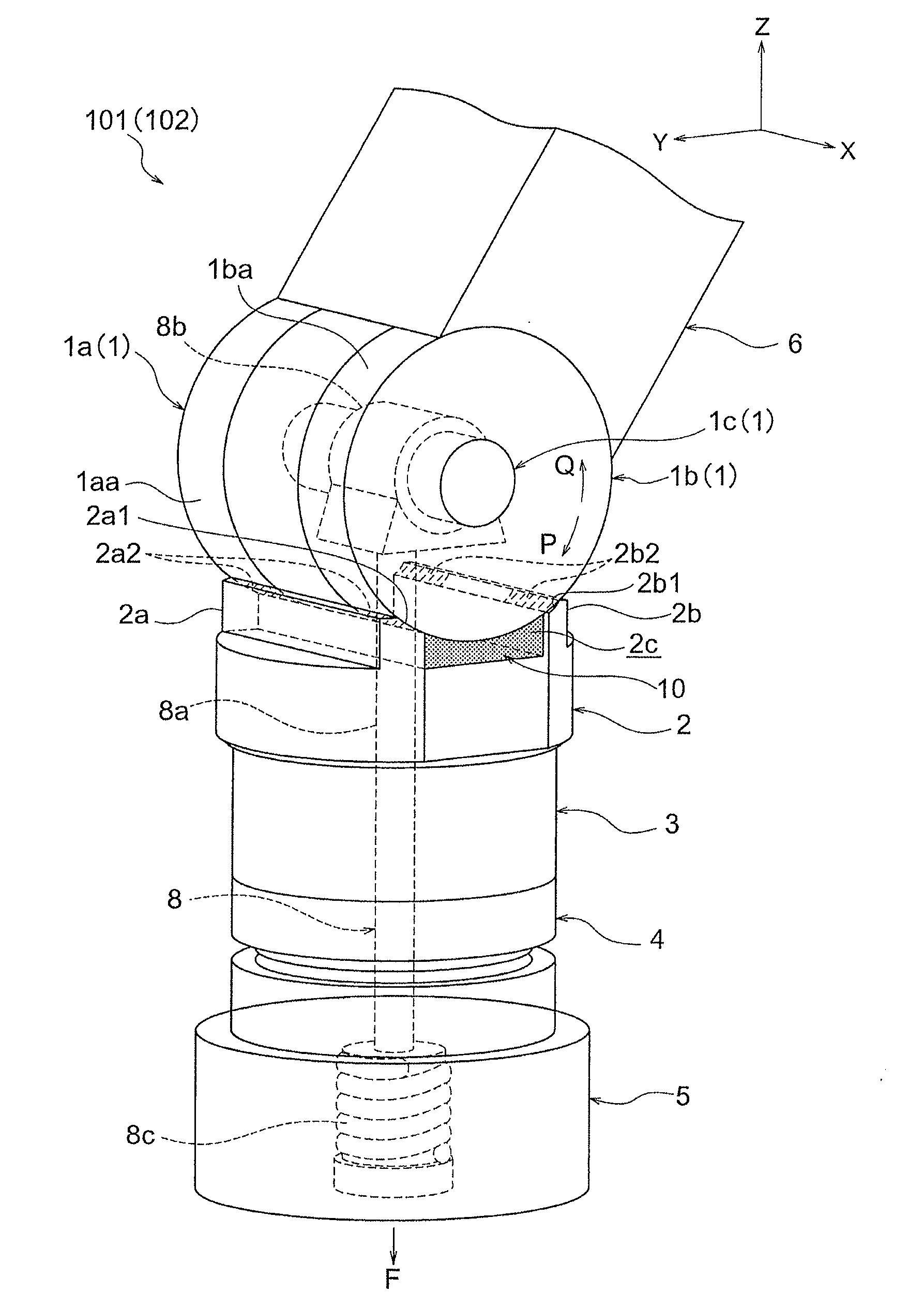
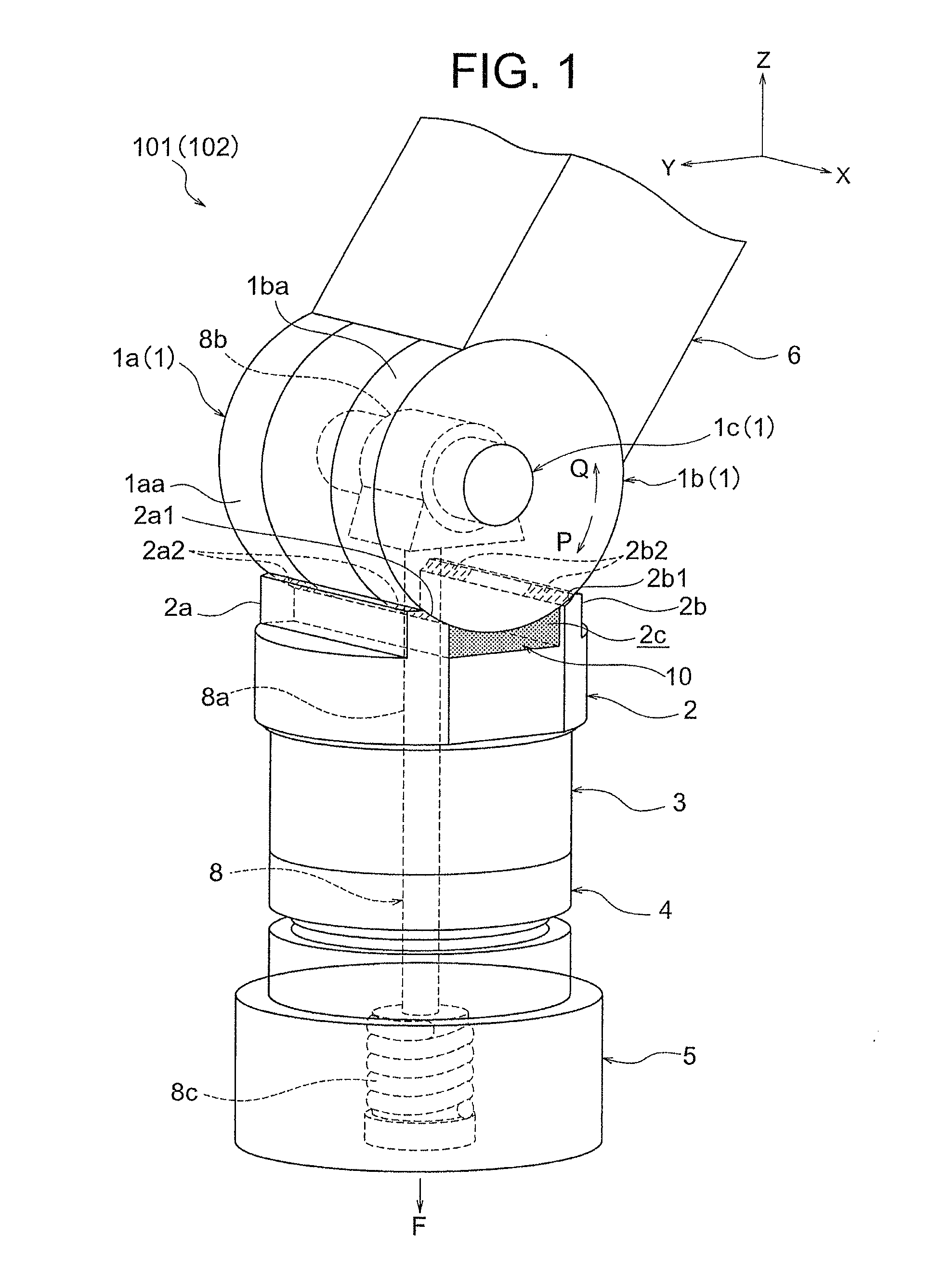
[0050]FIG. 1 shows an oscillation actuator 101 relating to this first embodiment. The oscillation actuator 101 causes a substantially cylindrical rotor 1 to rotate about an axial direction (see arrow P and arrow Q) using ultrasonic vibration, and is provided with an oscillator 2 which contacts the rotor 1 at one end side thereof. Furthermore, on the other end side of the oscillator 2, a piezoelectric element 3 which generates an ultrasonic vibration in the oscillator 2, and a first base block 4 and a second base block 5, are provided in this manner. The piezoelectric element 3 is formed by laminating together a plurality of piezoelectric plates, and ultrasonic vibrations are generated in the oscillator 2 by applying an AC voltage to the piezoelectric element plates, from a drive circuit (not illustrated). The oscillator 2 and the piezoelectric element 3 have a substantially cylindrical outer shape overall, and the axis direction of the rotor 1 is perpendicular to the axis directions...

second embodiment

[0095]Next, an oscillation actuator relating to a second embodiment of the invention will be described.

[0096]The oscillation actuator 102 relating to this second embodiment is configured so as to provide lubrication by using grease, as opposed to the oscillation actuator 101 of the first embodiment which uses oil for lubrication between the rotor 1 and the oscillator 2. Therefore, the oscillation actuator 102 relating to the second embodiment has the same configuration as the oscillation actuator 101 shown in FIG. 1.

[0097]The supply body 10 of the oscillation actuator 102 is impregnated with a grease having a base oil which is the oil used in the first embodiment, to which PTFE (polytetrafluoroethylene) is added as a thickener. Here, since the characteristics of grease are normally dependent on the characteristics of the base oil, then the grease used in the oscillation actuator 102 has the same characteristics as the oil used in the oscillation actuator 101.

[0098]In this way, even ...

third embodiment

[0099]Next, the oscillation actuator relating to a third embodiment of the invention will be described with reference to FIGS. 6 and 7. The oscillation actuator 103 relating to the third embodiment has a plurality of recesses formed in the outer circumferential surfaces 1aa, 1ba of the rotor 1 of the oscillation actuator 101 relating to the first embodiment. In the embodiments described below, reference symbols which are the same as those shown in FIG. 1 indicate constituent elements which are the same or similar, and therefore detailed description thereof is omitted here. Furthermore, in particular, the liquid lubricant with which the supply body 10 is impregnated is a fluorine-based oil having a viscosity at 40° C. of VG 400 according to the ISO viscosity classification, and is composed so to satisfy conditions (2) and (3) specified in the first embodiment.

[0100]As shown in FIG. 6, the oscillation actuator 103 is provided with a rotor 31 in which a plurality of recesses are formed...


PUM


Abstract

The oscillation actuator of the invention uses ultrasonic vibrations generated in a stator to rotate a rotor, and a pre-load member causes a 30 MPa contact pressure between the rotor and the stator. Furthermore, a supply body impregnated with oil is provided inside a recess section in the stator, such that the contact section between the rotor and the stator is lubricated by oil supplied from the supply body. As the oil with which the supply body is impregnated, a fluorine-based oil having a kinetic viscosity at 40° C. of VG 400 according to the ISO viscosity classification is selected.

Description

TECHNICAL FIELD[0001]This invention relates to an oscillation actuator which drives a moving element using ultrasonic vibrations generated in an oscillator.BACKGROUND ART[0002]In recent years, oscillation actuators have been proposed, which generate ultrasonic vibrations in an oscillator including a piezoelectric element and thereby drive a moving element pressed in contact with the oscillator by means of the frictional force between the oscillator and the moving element. In an oscillation actuator, if there is a change in the pressure contact force between the oscillator and the moving element, due to wear of the sliding portions thereof, then variation occurs in the characteristics, such as torque, the number of revolutions, etc. Therefore, in order to prevent or reduce such variation in the characteristics, it is common to use, for example, a solid lubricant such as molybdenum disulphide or graphite, to lubricate the sliding portions.[0003]Patent Document 1, for example, describe...

Claims


Application Information

Patent Timeline
Patent Type & Authority Applications(United States)
IPC IPC(8): H02N2/16H02N2/00H01L41/09
CPCH02N2/16H02N2/0065H01L41/09H02N2/0025H02N2/103H02N2/108F01L2810/02H10N30/20
Inventor ASAI, SHINYATAKASAN, MASAKISUZUKI, AKIHIROGODA, YASUYUKIMAKISHI, WATARU
Owner TOYOTA IND CORP
Why Eureka
Try Eureka