Reactor

a technology of reactors and inductances, applied in the field of reactors, can solve the problems of increasing the inductance of the reactor, requiring the downsizing of such a reactor, etc., and achieve the effects of increasing the inductance, facilitating cooling, and increasing the size of the reactor

Inactive Publication Date: 2014-10-30
TOYOTA JIDOSHA KK
View PDF3 Cites 13 Cited by
  • Summary
  • Abstract
  • Description
  • Claims
  • Application Information

AI Technical Summary

Benefits of technology

[0007]A reactor used for a power converter tends to be large in size as it handles a large current. Meanwhile, downsizing of such a reactor has been demanded for installation in a hybrid electric vehicle and the like. In addition, due to a large amou

Problems solved by technology

Meanwhile, downsizing of such a reactor has been demanded for installation in a hy

Method used


Image

  • Reactor
  • Reactor
  • Reactor

Examples


Embodiment Construction

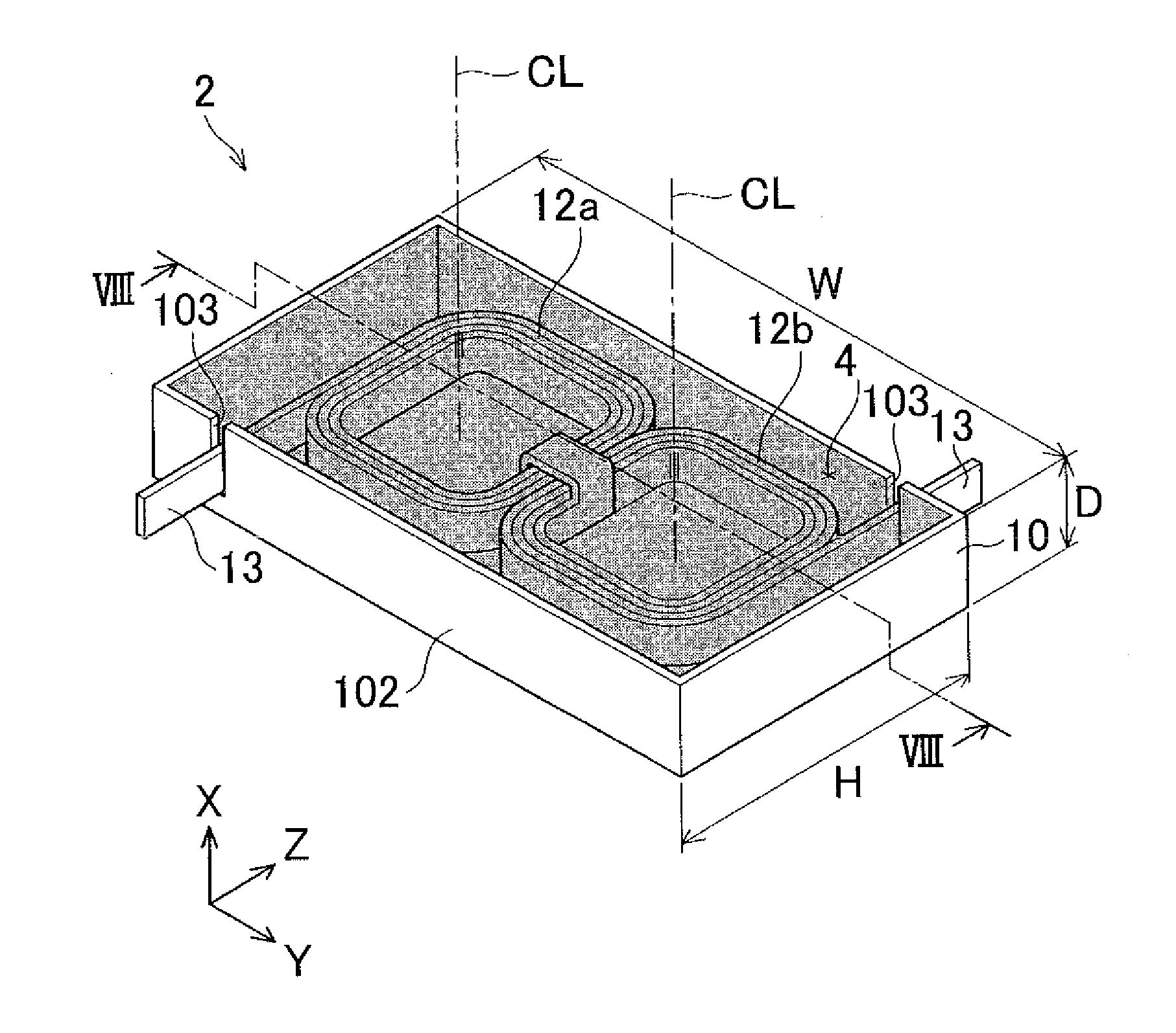
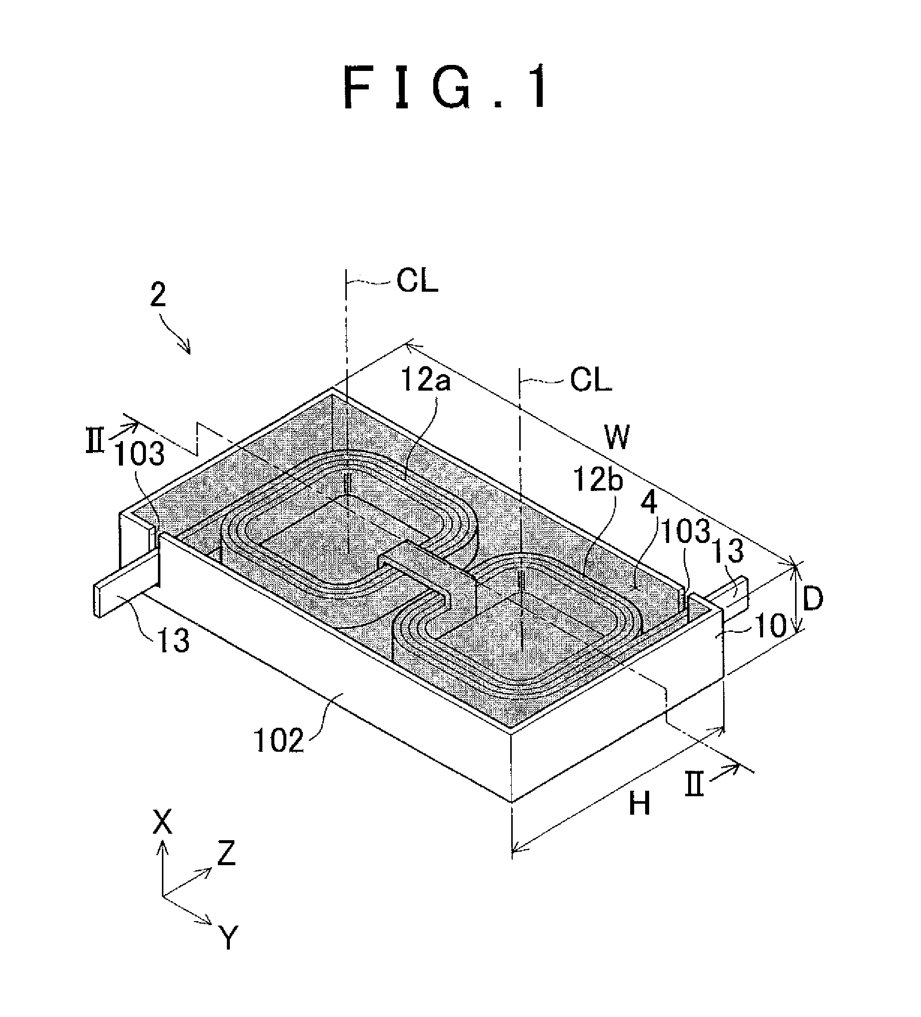
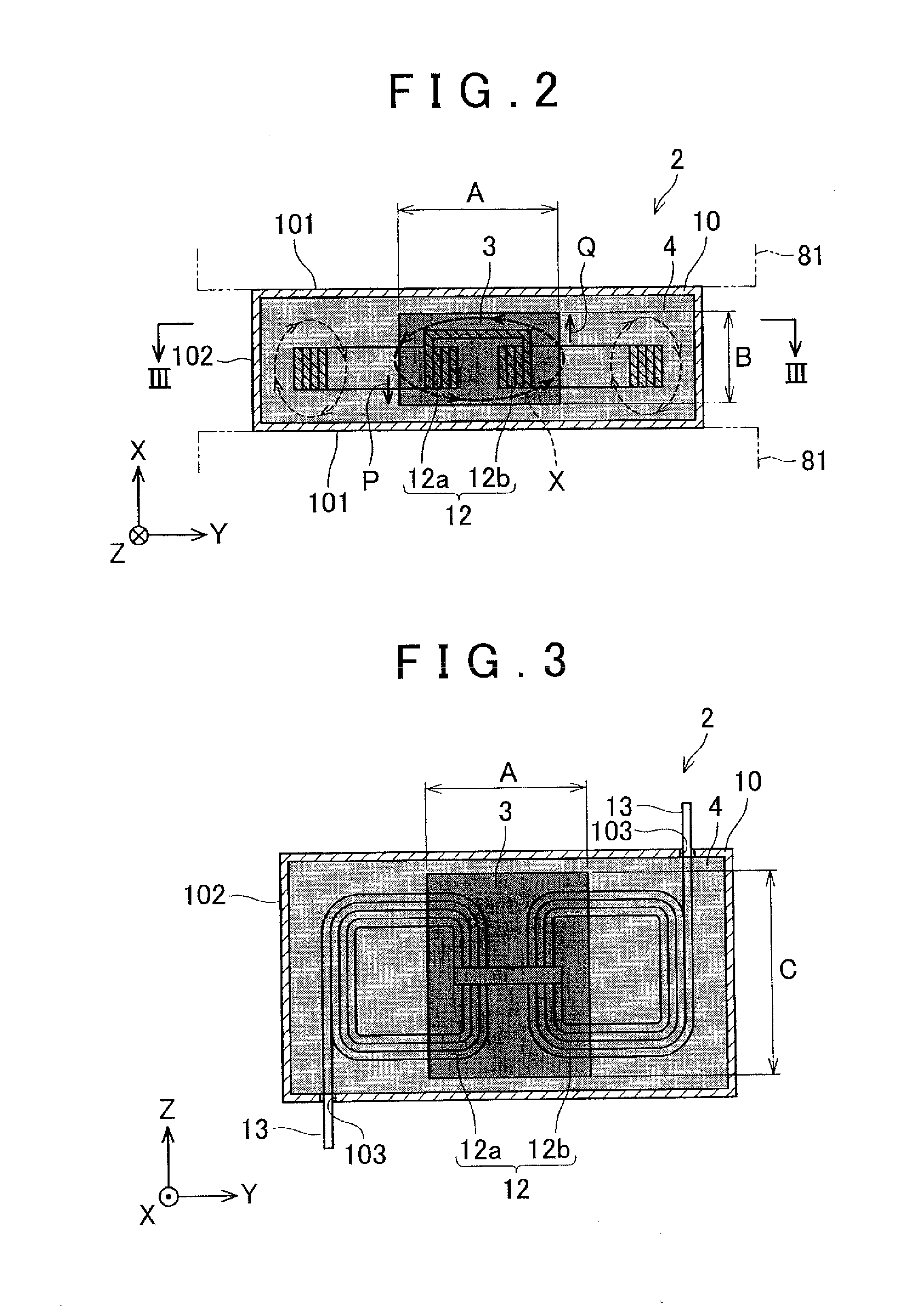
[0025]A description will hereinafter be made on embodiments with reference to the accompanying drawings. FIG. 1 is a perspective view of a reactor according to an embodiment. FIG. 2 is a cross-sectional view taken along the line II-II of FIG. 1, and FIG. 3 is a cross-sectional view taken along the line III-III of FIG. 2. In FIG. 1, a part of a case (flat case) 10 is opened so that a configuration of a reactor 2 can easily be seen. The reactor 2 is disposed between stacked coolers 81, which will be described below. As shown in FIG. 1 to FIG. 3, the reactor 2 includes the case 10 and a pair of coils 12 (a first coil 12a and a second coil 12b) that are disposed in the case 10. The case 10 is of flat shape. The reactor 2 also includes core materials (a high-permeability core material 3 and a low-permeability core material 4) filled in the case 10. The high-permeability core material 3 is not seen in FIG. 1 because it is covered by the low-permeability core material 4. The coils 12 are a...


PUM


Abstract

A reactor that can be disposed between stacked coolers, the reactor includes a flat case, a pair of coils, and core material. The pair of coils is (i) located in the flat case, (ii) wound in opposite directions from each other, and (iii) disposed adjacent to each other in a radial direction of the coils. The core material is covering the coils in the flat case.

Description

INCORPORATION BY REFERENCE[0001]The disclosure of Japanese Patent Application No. 2013-093241 filed on Apr. 26, 2013 including the specification, drawings and abstract is incorporated herein by reference in its entirety.BACKGROUND OF THE INVENTION[0002]1. Field of the Invention[0003]The present invention relates to a reactor that includes a coil.[0004]2. Description of Related Art[0005]A power converter that converts output power of a battery to suitable power for driving a traveling motor is mounted in an electric vehicle such as a hybrid electric vehicle. Because this electric converter handles a large current, devices with a large allowable current are adopted for use in an inverter circuit and a voltage converter circuit. The devices with the large allowable current generate a large amount of heat, and one of the devices that generate the particularly large amount of heat is a reactor included in the voltage converter circuit.[0006]As for a reactor, a technique disclosed in Japa...

Claims


Application Information

Patent Timeline
IPC IPC(8): H01F27/02H01F27/28
CPCH01F27/28H01F27/02H01F27/08H01F27/255H01F27/2847H01F37/00H02M7/003
Inventor NOBUSAKA, MAOATSUMI, TAKASHI
Owner TOYOTA JIDOSHA KK
Why Eureka
Try Eureka