Sliding thermal contact for pluggable optic modules

Active Publication Date: 2014-10-30
LUMENTUM OPERATIONS LLC
View PDF3 Cites 31 Cited by
  • Summary
  • Abstract
  • Description
  • Claims
  • Application Information

AI Technical Summary

Problems solved by technology

A fundamental problem for all pluggable (removable) optical modules in telecom systems is that the need to make them removable limits the thermal conduction path.
Improvements to the thermal conduction path will reduce the need for faster cooling air speeds or larger heat sinks, which are not always capable of keeping the modules within the operating temperature ranges specified.
Thermal contact resistance causes large temperature drops at the interfaces, which negatively affect the

Method used


Image

  • Sliding thermal contact for pluggable optic modules
  • Sliding thermal contact for pluggable optic modules
  • Sliding thermal contact for pluggable optic modules

Examples


Embodiment Construction

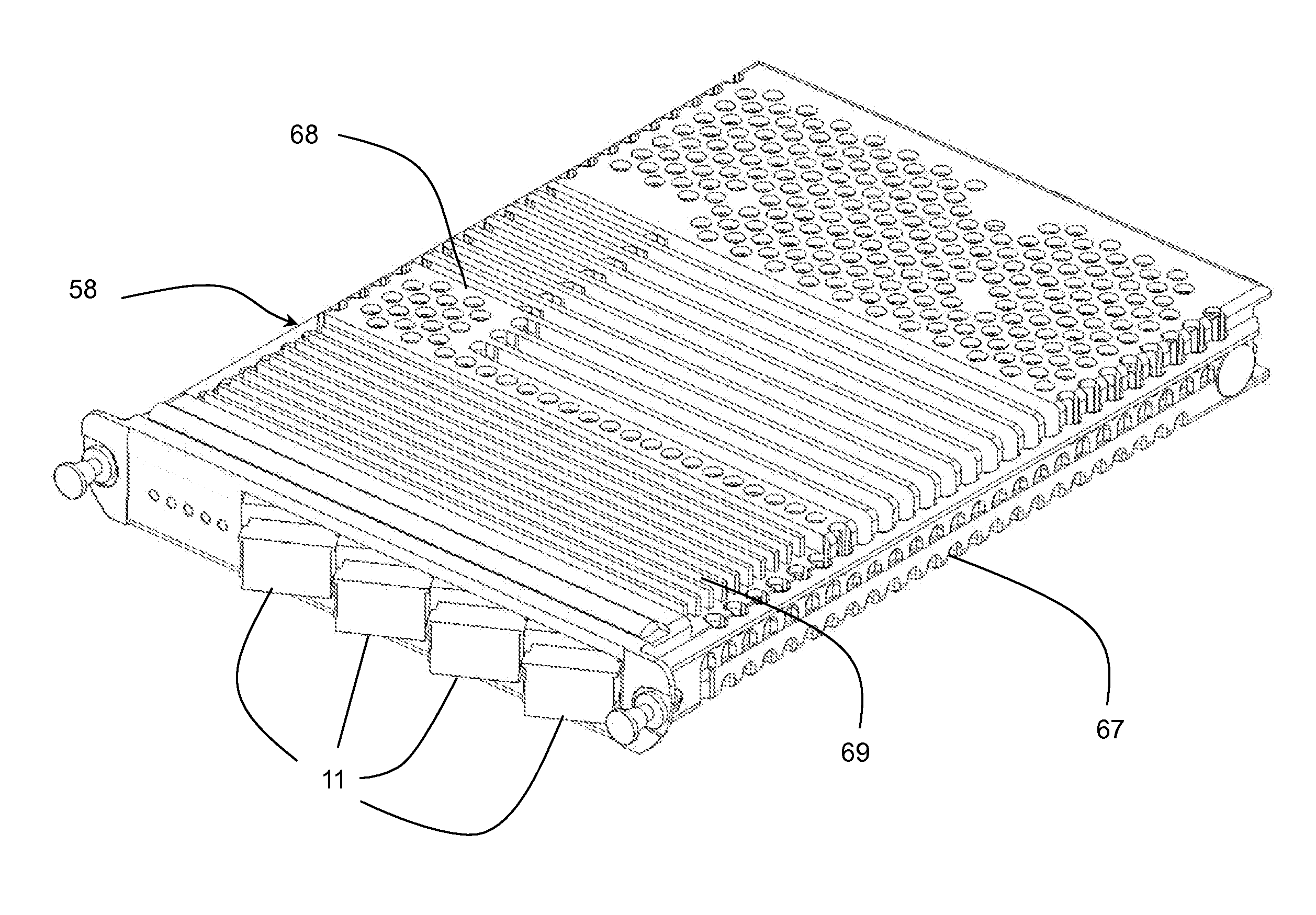
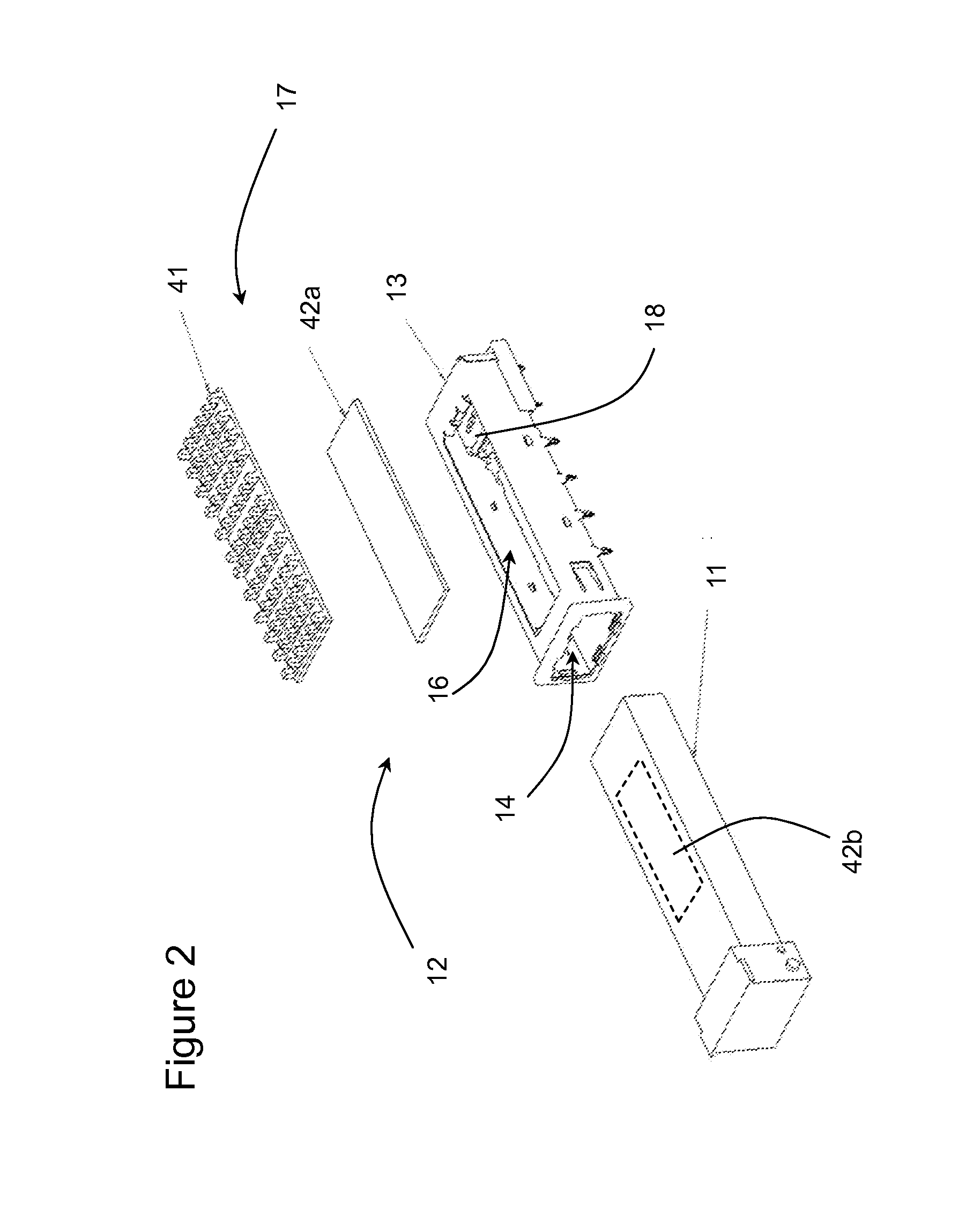
[0035]With reference to FIGS. 2 and 3, the present invention relates to a cage assembly 12 for receiving a pluggable optical module 11. The cage assembly 12 includes a rectangular, metal cage 13, as is known in the prior art, mounted on a printed circuit board 15, as in FIG. 1. The cage 13 includes a first opening 14 in a front wall for receiving the pluggable optical module 11, and a second opening 16 in an upper wall for receiving a heat sink assembly 17. The second opening 16 is at least half of the area of the upper wall, and preferably at least ¾ of the area of the upper wall, e.g. up to 90% of the area of the upper wall. An electrical connector 18 is mounted in the cage 13 on the printed circuit board for receiving a mating electrical connector on the pluggable optical module. The printed circuit board 15 includes trace electrical connectors for electrically connecting the connector 18 to a host computer system, within which the printed circuit board 15 is received.

[0036]The o...


PUM

PropertyMeasurementUnit
Lengthaaaaaaaaaa
Lengthaaaaaaaaaa
Fractionaaaaaaaaaa

Abstract

Present thermal solutions to conduct heat from pluggable optical modules into heat sinks use a metal heat sink attached with a spring clip. The interface between the pluggable module and the heat sink is simple metal-on-metal contact, which is inherently a poor thermal interface and limits heat dissipation from the optical module. Heat dissipation from pluggable optical modules is enhanced by the application of thermally conductive fibers, such as an advanced carbon nanotube velvet. The solution improves heat dissipation while preserving the removable nature of the optical modules.

Description

CROSS-REFERENCE TO RELATED APPLICATIONS[0001]The present invention claims priority from U.S. Patent Application No. 61 / 817,382 filed Apr. 30, 2013, which is incorporated herein by reference.TECHNICAL FIELD[0002]The present invention relates to an optical module, and in particular to a sliding heat sink for a pluggable optical module.BACKGROUND OF THE INVENTION[0003]Conventionally, optical transceivers with data rates up to 4 Gb / s are packaged in small form factor (SFF or SFP) packages, while optical transceivers with higher data rates, e.g. 10 Gb / s, are in larger packages, such as XFP, X2, and XENPAK. A conventional XFP arrangement is illustrated in FIG. 1, in which an XFP transceiver module 1 is plugged into a host cage assembly 2 mounted on a host circuit board 3. The host cage assembly 2 includes a front bezel 4, a cage receptacle 5, and a host electrical connector 6. The transceiver module 1 is inserted through an opening in the front bezel 4, and through an open front of the ca...

Claims


Application Information

Patent Timeline
IPC IPC(8): H05K7/20
CPCH05K2201/066H05K7/2039G02B6/4269B32B7/12B32B27/06B32B27/281G02B6/428H05K1/18H05K3/301H05K7/20H05K7/20409H05K7/20418H05K9/0058H05K2201/06H05K2201/10121H05K2201/10962
Inventor MOORE, DAVIDFLOCKTON, DEAN
Owner LUMENTUM OPERATIONS LLC
Why Eureka
Try Eureka