Transmission device, reception device, transmission method, and reception method

a transmission device and reception technology, applied in the field of transmission devices, reception devices, transmission methods, reception methods, etc., can solve the problems of greatly degrading the ber characteristics of the entire system, and achieve the effects of improving the ber characteristics, stabilizing reception, and expanding the coverage area

Inactive Publication Date: 2014-10-30
NIPPON HOSO KYOKAI
View PDF0 Cites 17 Cited by
  • Summary
  • Abstract
  • Description
  • Claims
  • Application Information

AI Technical Summary

Benefits of technology

[0025]According to the present invention, in a MIMO system performing SDM-MIMO transmission, BER characteristics can be improved by interleaving between polarized waves. Hence, the coverage area can be expanded and reception can be stabilized.

Problems solved by technology

With SDM transmission, since different streams are transmitted over the antennas, the Bit Error Rate (BER) characteristics of the entire system greatly degrade due to degradation of the BER characteristics resulting from a lower reception level for one antenna.

Method used


Image

  • Transmission device, reception device, transmission method, and reception method
  • Transmission device, reception device, transmission method, and reception method
  • Transmission device, reception device, transmission method, and reception method

Examples


embodiment 1

[Transmission Device]

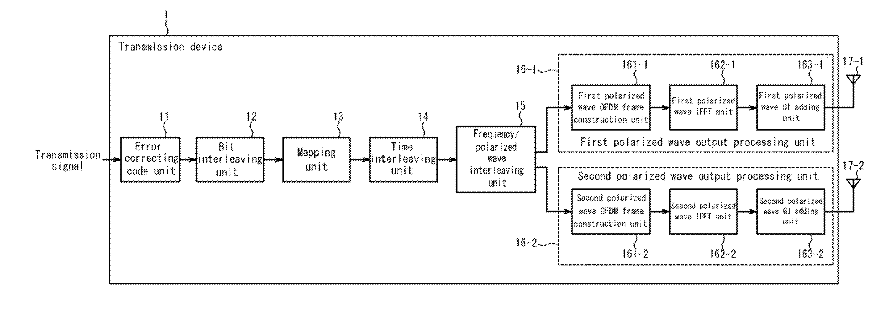
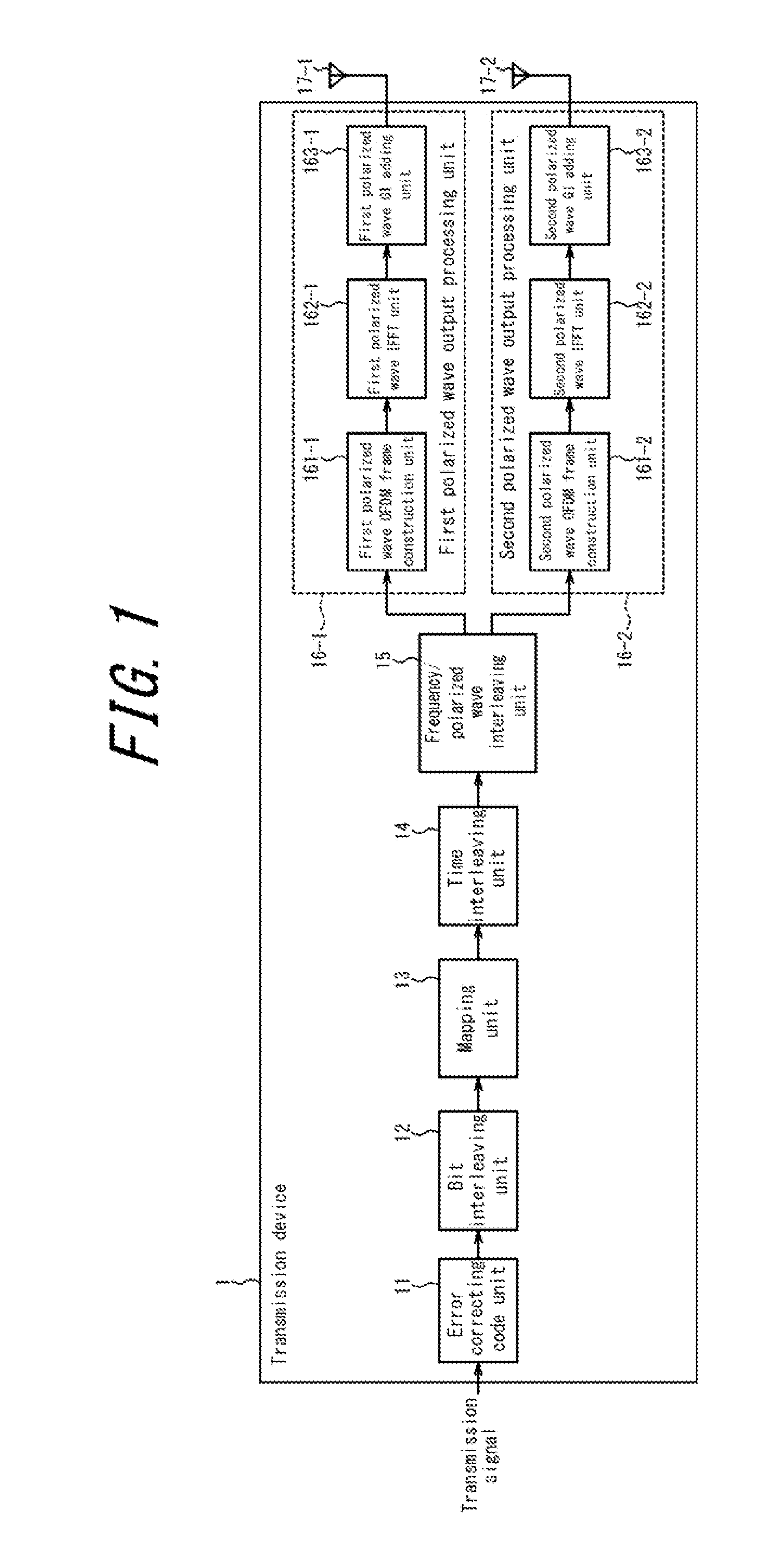
[0053]First, the transmission device according to Embodiment 1 of the present invention is described. The transmission device transmits an OFDM signal using different polarized waves from a plurality of transmit antennas. FIG. 1 is a block diagram illustrating the structure of the transmission device according to Embodiment 1 of the present invention. As illustrated in FIG. 1, a transmission device 1 includes an error correcting code unit 11, a bit interleaving unit 12, a mapping unit 13, a time interleaving unit 14, a frequency / polarized wave interleaving unit 15, a first polarized wave output processing unit 16-1, a second polarized wave output processing unit 16-2, a first polarized wave transmit antenna 17-1, and a second polarized wave transmit antenna 17-2. The first polarized wave output processing unit 16-1 includes a first polarized wave OFDM frame construction unit 161-1, a first polarized wave IFFT unit 162-1, and a first polarized wave GI adding unit...

embodiment 2

[0115]Next, in Embodiment 2, the case of transmitting one data stream simultaneously over a plurality of channels (referred to below as bulk transmission) is described, i.e. the case of the transmission device using a plurality of transmit antennas per channel to transmit an OFDM signal over a plurality of channels and the reception device using a plurality of receive antennas per channel to receive the OFDM signal over a plurality of channels. Embodiment 2 describes an example in which the number of channels is two, yet the number of channels is not limited to two.

[0116][Transmission Device]

[0117]FIG. 16 is a block diagram illustrating the structure of a transmission device 3 according to Embodiment 2 of the present invention. The error correcting code unit 11, bit interleaving unit 12, mapping unit 13, and time interleaving unit 14 perform the same processing as Embodiment 1 for the transmission signals over two channels.

[0118]A frequency / polarized wave / channel interleaving unit 1...


PUM


Abstract

In a MIMO system performing MIMO transmission using a plurality of antennas, BER characteristics are improved. A transmission device includes a mapping unit that maps a transmission signal onto the IQ plane to generate carrier-modulated carrier symbols, a frequency / transmit antenna interleaving unit (frequency / polarized wave interleaving unit) that interleaves the carrier symbols in the frequency domain and between transmit antennas to generate interleaved data for each transmit antenna, and an output processing unit that constructs an OFDM frame for the interleaved data for each transmit antenna and transmits an OFDM signal via the transmit antennas.

Description

CROSS-REFERENCE TO RELATED APPLICATION[0001]This application claims priority to and the benefit of Japanese Patent Application No. 2011-253146 filed Nov. 18, 2011 and Japanese Patent Application No. 2012-183571 filed Aug. 22, 2012, the entire contents of which are incorporated herein by reference.TECHNICAL FIELD[0002]The present invention relates to a transmission device, reception device, transmission method, and reception method that perform Multiple Input Multiple Output (MIMO) transmission using a plurality of different antennas. In particular, the present invention relates, in a MIMO system, to a transmission device that performs interleaving between a plurality of antennas, a reception device that performs deinterleaving between a plurality of antennas, and methods thereof.BACKGROUND ART[0003]ISDB-T (Integrated Services Digital Broadcasting-Terrestrial), which is a digital terrestrial broadcasting system in Japan, implements high-vision broadcasting (or multiple standard defin...

Claims


Application Information

Patent Timeline
Patent Type & Authority Applications(United States)
IPC IPC(8): H04B7/06H04L27/26H04B7/04
CPCH04B7/0697H04L27/2626H04B7/0413H04B7/068H04B7/0848H03M13/1165H03M13/152H03M13/2906H04L1/0071H04L2001/0093H04B7/10H04L1/06
Inventor ASAKURA, SHINGOMURAYAMA, KENICHITAGUCHI, MAKOTOSHITOMI, TAKUYASHIBUYA, KAZUHIKO
Owner NIPPON HOSO KYOKAI
Why Eureka
Try Eureka