Controller

a controller and controller technology, applied in the field of controllers, can solve the problems of limited control of a controller of this type, inability to achieve quick recognition and avoid false recognition at the same time, and achieve the effect of high reliability

Active Publication Date: 2014-10-30
MIZUNO YOSHIRO
View PDF4 Cites 6 Cited by
  • Summary
  • Abstract
  • Description
  • Claims
  • Application Information

AI Technical Summary

Benefits of technology

[0011]The technique disclosed in Patent Literature 1 lacks the consideration on shapes to be recognized by the controller. Setting an inappropriate shape as a cue sign can lead to false recognition. The objective of the present disclosure is to provide a highly reliable controller in which a shape less susceptible to false recognition is set as a cue sign.
[0013]Further, another objective is to provide a controller including a recognition algorithm that is capable of recognizing a cue sign with reasonable resources and time.
[0022]The shape of a paper sign includes projections and indentations which are suitable for pattern recognition. Choosing this shape has the effect of reducing resources required for recognition and recognition time. Among various shapes that have been studied in the field of gesture recognition, the shape of a paper sign has a significant effect of improving recognition when a recognition program using features relating to the thumb is chosen because the thumb, which has features that can be readily identified, is clear in the shape of a paper sign.
[0024]If the time of recognition of a cue sign is to be set as the timing of control, the controller will not be easy to use for the user because there is a delay in recognition due to external factors. It will be difficult to perform control at the moment that the user desires. On the other hand, a delay is very unlikely to occur at a moment after recognition and at which the recognition is no longer sensed. Therefore, the setting of the timing has the effect of allowing the controller to stably perform a control at a timing close to the timing intended by the user by changing the shape of the cue sign or pulling the fingers away from the image capturing range at the moment when the user wants to control.
[0034]There is a limit to the number of shapes that can be formed by a hand which are suitable for recognition. By differentiating between the right and left hands, the number of cue signs can be increased. As a result, the variety of pieces of equipment and operations that can be controlled is increased.
[0044]The thermal image sensor is capable of obtaining an image that clearly captures the shape formed by fingers even in darkness. Since the thermal image sensor works regardless of the brightness in a place where the controller is used, the use of the thermal image sensor has the effect of increasing the range of places and environments in which the controller can be used. Furthermore, since the difference in temperature between the background and fingers forming a cue sign is large in an ordinary environment, the shape formed by the fingers can readily be separated from the background. This has the effect of achieving accurate and fast recognition by the controller.

Problems solved by technology

However, controlling by a controller of this type is limited to the simple on-off operation controls of equipment such as lighting equipment.
However, the method has a problem concerning an appropriate selection of a finger pose and a problem that quick recognition and avoidance of false recognition cannot be achieved at the same time.

Method used


Image

  • Controller
  • Controller
  • Controller

Examples


first embodiment

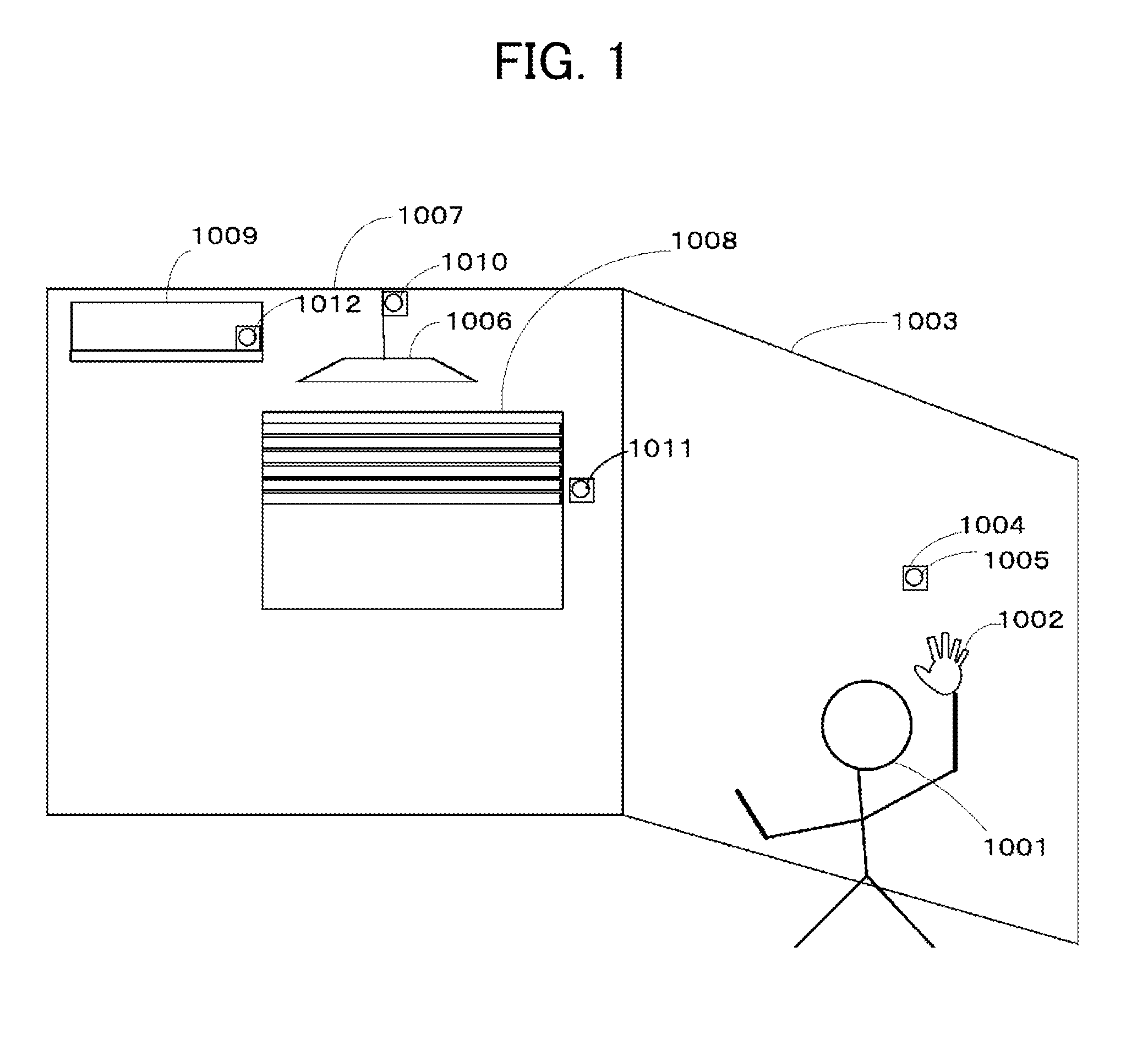
[0066]FIG. 1 is a conceptual diagram of a room equipped with controllers of the present disclosure. A user 1001 is at the entrance of the room. In the situation illustrated in the figure, the user 1001 directs fingers 1002 to a controller 1004 provided on a sidewall 1003 and is waving the hand in the shape of a paper sign. The controller 104 is provided with an image sensor unit 1005, which is generating images at predetermined intervals.

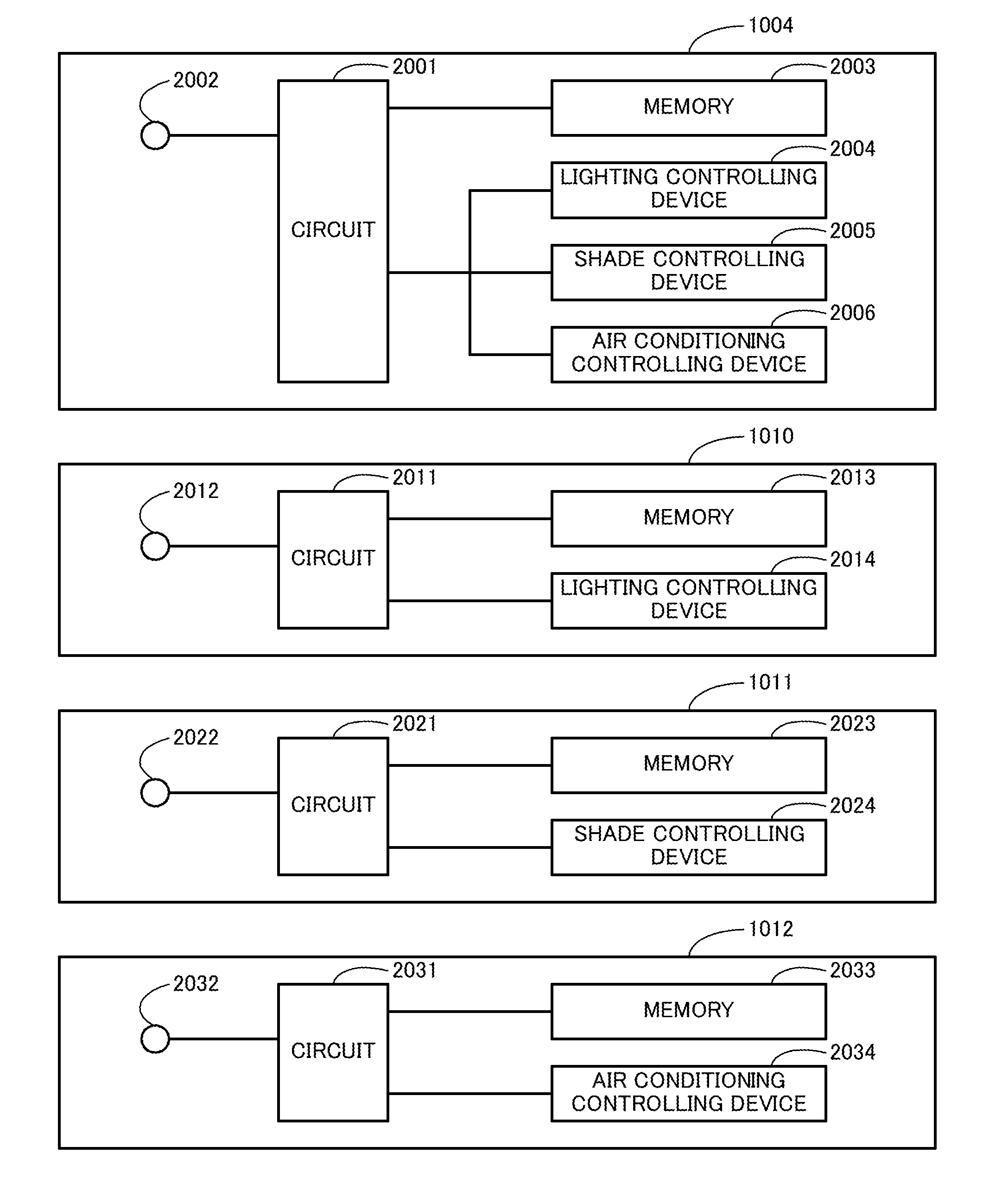
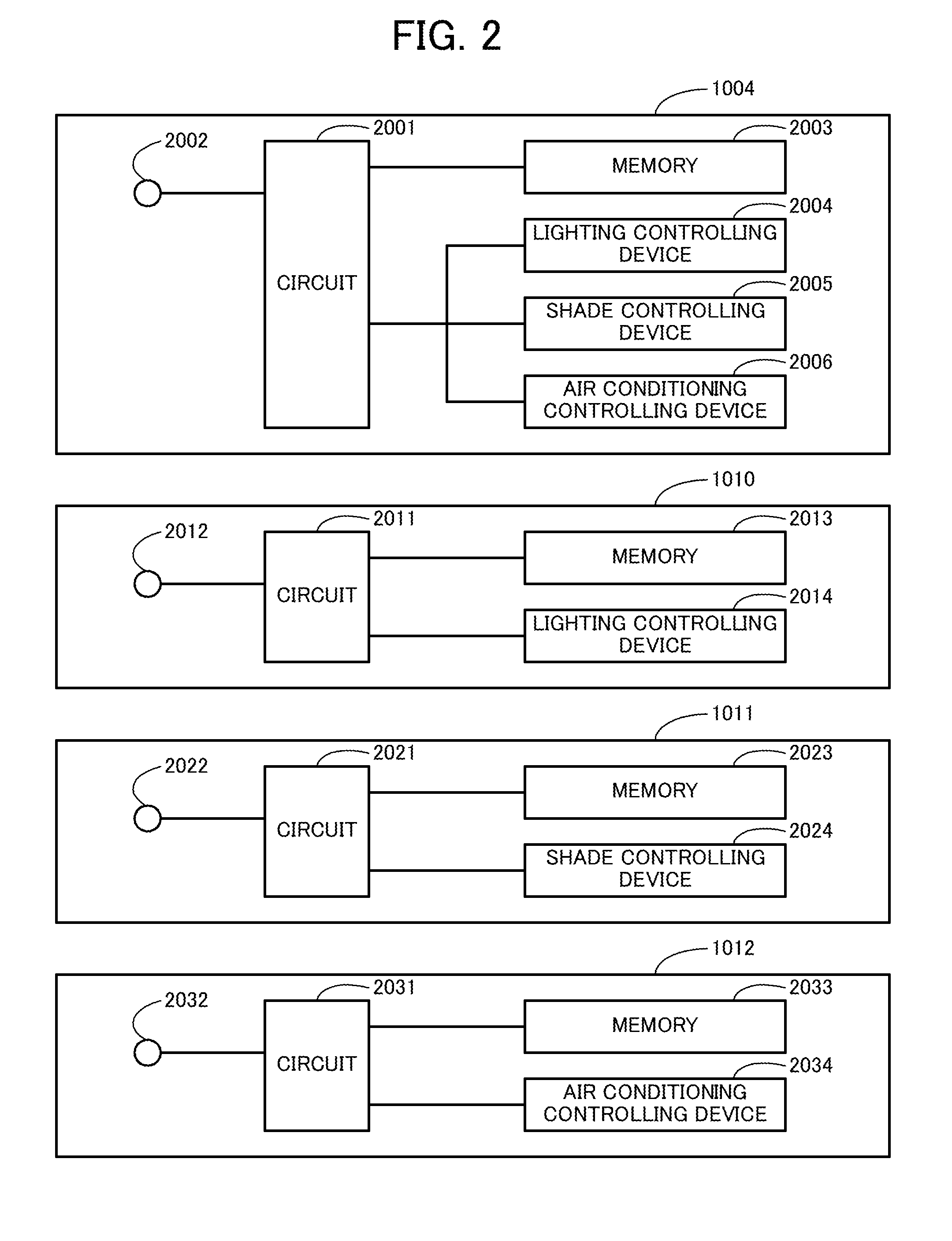
[0067]Lighting equipment 1006 is provided on the ceiling. A window is provided in the wall 1007 facing the entrance. A shade 1008 including an electrical roll-up function is provided at the window. An air conditioner 1009 is provided at the top of the wall facing the entrance. 1010 denotes a controller provided for the lighting equipment. The controller includes an image sensor unit. The user 1001 can operate the equipment with a predetermined cue sign or by performing an action with a predetermined cue sign toward the sensor unit. 1011 denotes a co...

second embodiment

[0121]A second embodiment has a configuration in which a controller of the present disclosure is built in a handheld information terminal with built-in camera.

[0122]FIG. 6 is a conceptual drawing of a user operating a handheld information terminal with built-in camera in which a controller of the present disclosure is used.

[0123]The control function of the controller is implemented by a preinstalled control program such as firmware being executed by a processor or control circuit of an information terminal with built-in camera and cooperating with devices such as an image sensor unit constituting the information terminal with built-in camera. Such programs are recorded on a computer-readable recording medium, are read from the recording medium by the processor or the control circuit, and are executed in response to an operation by a user or a signal from a device constituting the information terminal with built-in camera.

[0124]FIG. 7 is a block diagram of a controller and devices of...

third embodiment

[0135]In a third embodiment, a control device of the present disclosure is built in a television set. FIG. 9 is a conceptual drawing of a user operating a television set to which a control device of the present disclosure is applied. In this figure, the user 9001 forms a cue sign 9004 and directs the cue sign to an image sensor unit 9003 provided for a television set 9002.

[0136]FIG. 10 is a block diagram illustrating a controller and various devices of the terminal.

[0137]10001 denotes a controller circuit. The circuit may be implemented as a part of the circuitry of the terminal.

[0138]10002 denotes the image sensor unit.

[0139]10003 denotes a memory, in which a cue sign storage and an association storage are provided.

[0140]10004 denotes a channel controlling device, which controls channel switching.

[0141]1005 denotes a sound volume controlling device, which controls the sound volume of a speaker.

[0142]10006 denotes a power switch controlling device, which controls turning on and off ...


PUM


Abstract

An objective of the present disclosure is to provide a highly reliable controller in which shapes that are not susceptible to false recognition are set as cue signs. The controller includes a control circuit which is implemented by a microcomputer or the like, an image sensor unit, and a memory. The control circuit is connected to a lighting controlling device of lighting equipment, a shade controlling device of a shade, and an air conditioning control device of an air conditioner through a communication link. A user can operate these pieces of equipment with a predetermined cue sign or an action with a predetermined cue sign.

Description

TECHNICAL FIELD[0001]The present invention relates to a controller for various electric appliances, information terminals, indoor and outdoor equipment, game clocks and the like and, in particular, to a controller using an image sensor.BACKGROUND ART[0002]To operate a typical controller for various electric appliances, information devices, indoor or outdoor equipment or the like, a user need to directly touch the controller. Specifically, a user needs to perform operations such as pressing, turning or moving buttons, icons or the like on a controller equipped with such buttons, icons or the like. A remote control for remotely operating equipment allows a user to operate the equipment to be operated without directly touching the equipment. However, the user needs to directly touch the remote control equipped with buttons, icons, or the like to operate the remote control.[0003]In board games such as go, shogi, and chess, a game clock is used for measuring the time each player takes fo...

Claims


Application Information

Patent Timeline
Patent Type & Authority Applications(United States)
IPC IPC(8): G06F3/01G05B15/02
CPCG05B15/02G06F3/017G08C17/00
Inventor MIZUNO, YOSHIRO
Owner MIZUNO YOSHIRO
Why Eureka
Try Eureka