
Proximity detection using sensors based on a programmable multi-array structures

a multi-array structure and sensor technology, applied in the field of proximity detection using sensors based on programmable multi-array structures, can solve the problems of no electronic product purchase incentive transmitted, wireless mobile devices, wireless mobile devices, etc., and achieve the effect of generating brand awareness

Inactive Publication Date: 2014-10-30
README SYST
View PDF0 Cites 113 Cited by
  • Summary
  • Abstract
  • Description
  • Claims
  • Application Information

AI Technical Summary

Benefits of technology

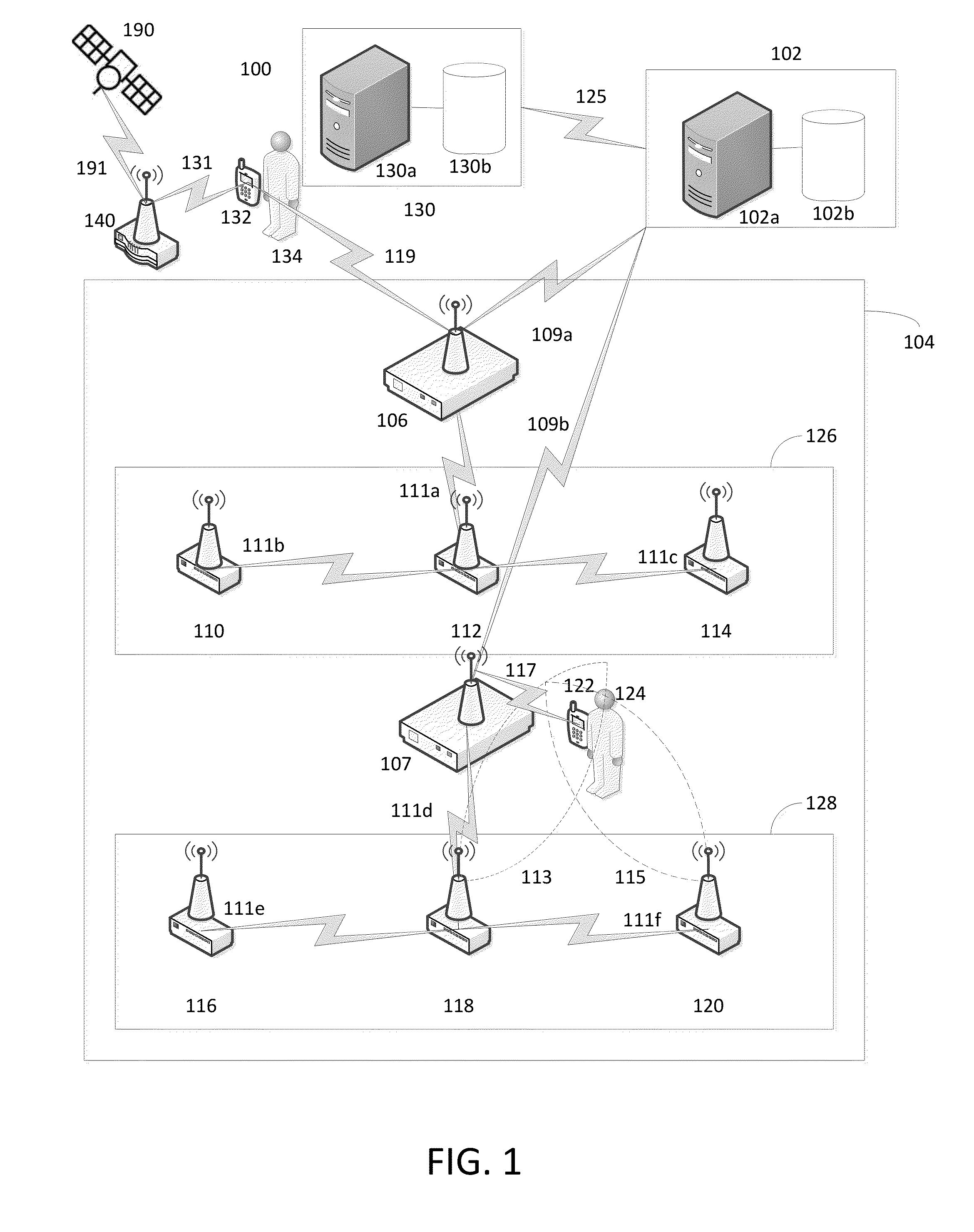
The patent describes a system that uses sensors to track the presence and location of shoppers' wireless devices in a retail environment. This information is used to engage shoppers in transaction-oriented interactions as they move through the aisles. This results in increased revenue for the retailers and better understanding of shopping behavior, which can be used to improve analytics.

Problems solved by technology

Further, in some embodiments, no electronic product purchase incentive is transmitted to a tagged wireless mobile device even though the predetermined threshold of time has been exceeded.
However, the wireless mobile device is designated as an untagged wireless mobile device when the tag module is not downloaded onto the wireless mobile device.
Radio receivers may have a low noise amplifier that increases power level of the input signal detected by the antenna (along with noise received by the antenna) but introduces only a small amount of noise itself.
Transmissions in other directions or planes are wasteful or may cause interference.
However, it may be that the control unit of the data sensor adjusts sensitivity, directivity, and power level of the second patch antenna of the data sensor to a low level and does not detect a presence of the wireless mobile device.
However, the sensor device may not detect (2306) the presence of the wireless mobile device when adjusting, by the control unit, the sensitivity, directivity, and power level of the first patch antenna to a low level.

Method used


Image

  • Proximity detection using sensors based on a programmable multi-array structures
  • Proximity detection using sensors based on a programmable multi-array structures
  • Proximity detection using sensors based on a programmable multi-array structures

Examples


Embodiment Construction

[0025]The illustrative embodiments described in the detailed description, drawings, and claims are not meant to be limiting. Other embodiments may be utilized, and other changes may be made, without departing from the scope of the subject matter presented herein. It will be readily understood that the aspects of the present disclosure, as generally described herein, and illustrated in the Figures, can be arranged, substituted, combined, separated, and designed in a wide variety of difference configurations, all of which are explicitly contemplated herein. Further, in the foregoing description, numerous details are set forth to further describe and explain one or more embodiments. These details include system configurations, block module diagrams, flowcharts (including transaction diagrams), and accompanying written description. While these details are helpful to explain one or more embodiments of the disclosure, those skilled in the art will understand that these specific details ar...


PUM


Abstract

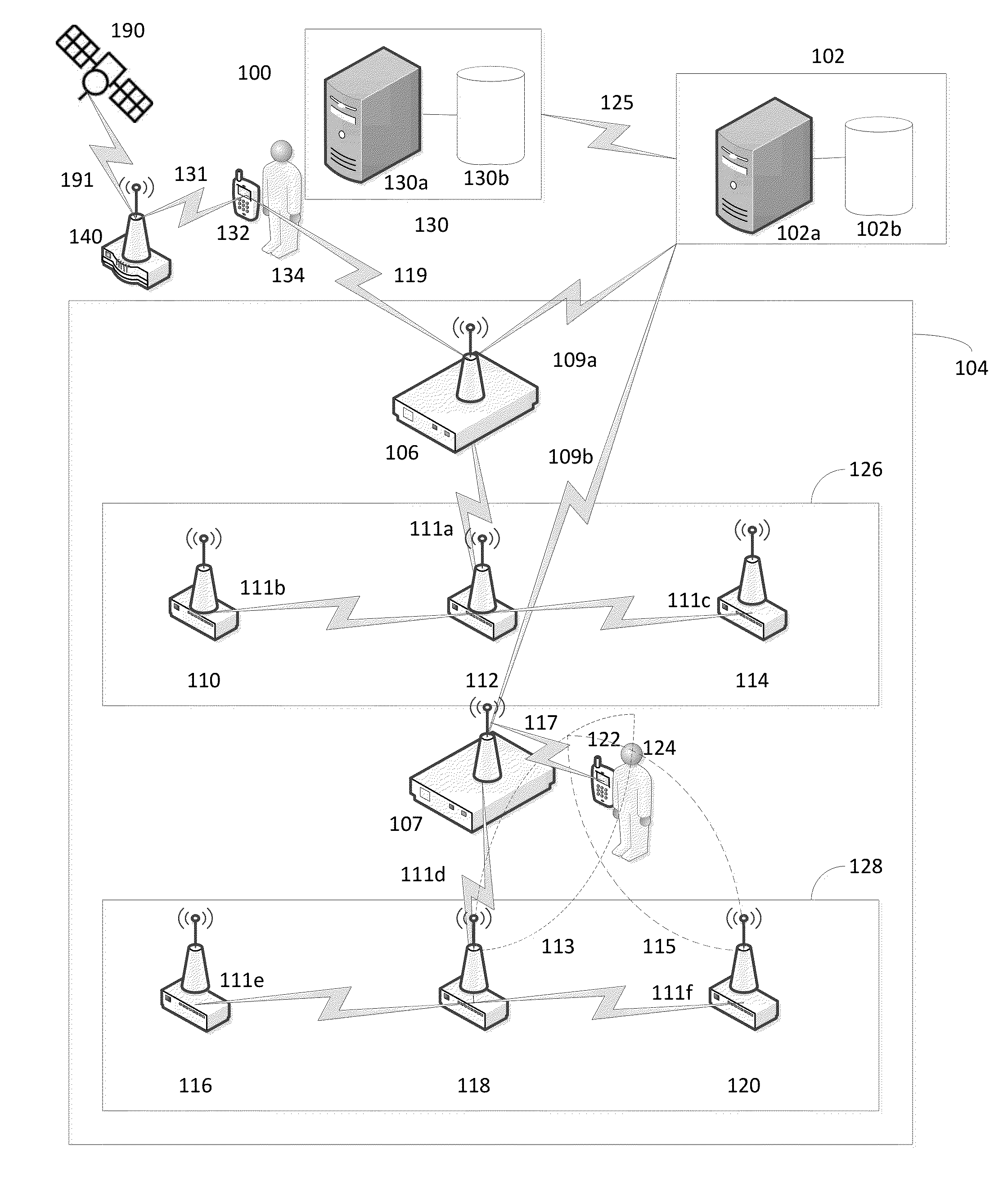
Embodiments of the present disclosure is directed to the use of spatially diverse multiple antenna structures and associated radio transmitters and receivers in a sensor for accurate proximity detection. In a retail environment, a system based on a network of such (smart) sensors can accurately detect presence and location of a shopper's wireless mobile device as the shopper moves along the shopping aisles carrying the wireless mobile device (e.g. smartphone). Based on the location of the shopper and the duration of the shopper stopping in front of a product shelf in an aisle, embodiments can engage the shopper (through the wireless mobile device) in transaction-oriented interactions using the ‘sense, analyze, and connect’ capability of the various embodiments described herein. Such interactions result in increased revenue for the retailers as well as better understanding of the shopping behavior of the retail shoppers. Such understanding can be embodied in improved analytics.

Description

CROSS-REFERENCE TO RELATED APPLICATIONS[0001]The present application is a continuation-in-part of U.S. patent application Ser. No. 14 / 072,742 filed on Nov. 5, 2013 the entire contents of which is being incorporated herein by reference.[0002]Further, U.S. patent application Ser. No. 14 / 072,742 filed on Nov. 5, 2013 claims benefit under the US law and rules including 35 U.S.C. §119(e) from U.S. Provisional Patent Application Ser. No. 61 / 815,935 filed on Apr. 25, 2013 the entire contents of which is being incorporated herein by reference.[0003]In addition, U.S. patent application Ser. No. 14 / 072,742 filed on Nov. 5, 2013 claims benefit under the US law and rules including 35 U.S.C. §119(e) from U.S. Provisional Patent Application Ser. No. 61 / 834,352 filed on Jun. 12, 2013 the entire contents of which is being incorporated herein by reference.[0004]The present application is related to U.S. patent application Ser. No. 14 / 072,750 (Techlaw Docket No. 13-090-B) titled “Systems, Methods, an...

Claims


Application Information

Patent Timeline
IPC IPC(8): G06Q30/02H04W4/02H04W4/50H04W4/80
CPCG06Q30/0261G06Q30/0267H04L61/6022H04W4/008H04L67/306G06F8/00H04W4/001H04L67/34H04W4/50H04W4/80H04L2101/622
Inventor KULKARNI, RAGHAVENDRAPATEL, SHIRISHDAS, SANTANU
Owner README SYST
Learn More