Radio frequency filter having cavity structure

a radio frequency filter and cavity structure technology, applied in the field of radio frequency filter having cavity structure, can solve the problems of loss, limit the size and weight of small-scale and lightweight, and achieve the effect of reducing the cost of radio frequency filter, convenient installation and simplified structur

Active Publication Date: 2014-11-06
KMW INC
View PDF5 Cites 14 Cited by
  • Summary
  • Abstract
  • Description
  • Claims
  • Application Information

AI Technical Summary

Benefits of technology

[0013]According to the present invention, a radio frequency filter having a cavity structure can be both small-scale and a lightweight, can allow frequency tuning without employing a coupling structure for tuning screws and fixing nuts, and can have a simplif...

Problems solved by technology

However, the installation method causes a loss problem due to connections of cables between the antenna apparatus and the body apparatuses and an installation space problem of the body apparatus.
However, because a radio frequency filter having a cavity structure includes a resonance element in a housing and...

Method used


Image

  • Radio frequency filter having cavity structure
  • Radio frequency filter having cavity structure
  • Radio frequency filter having cavity structure

Examples


fifth embodiment

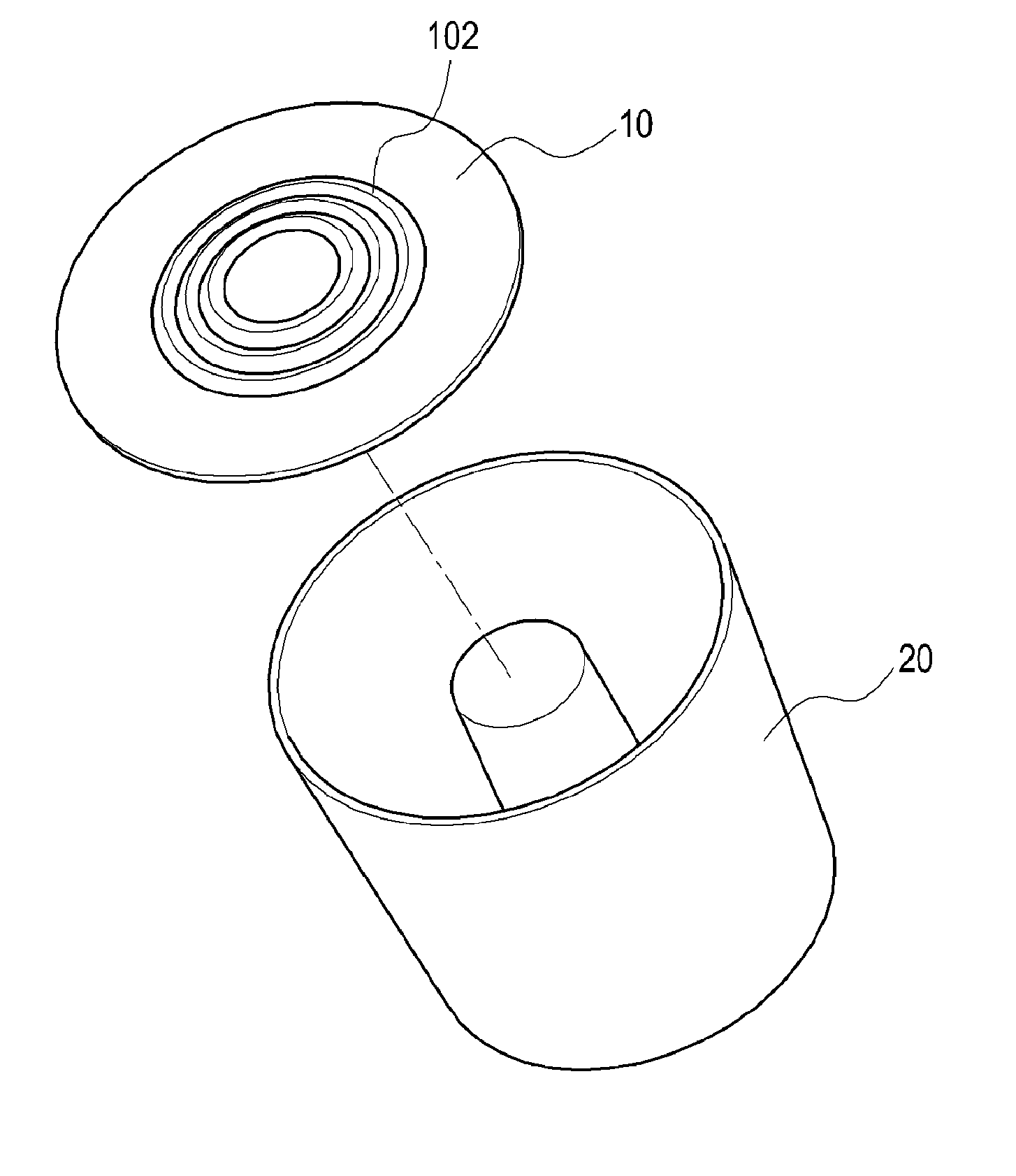
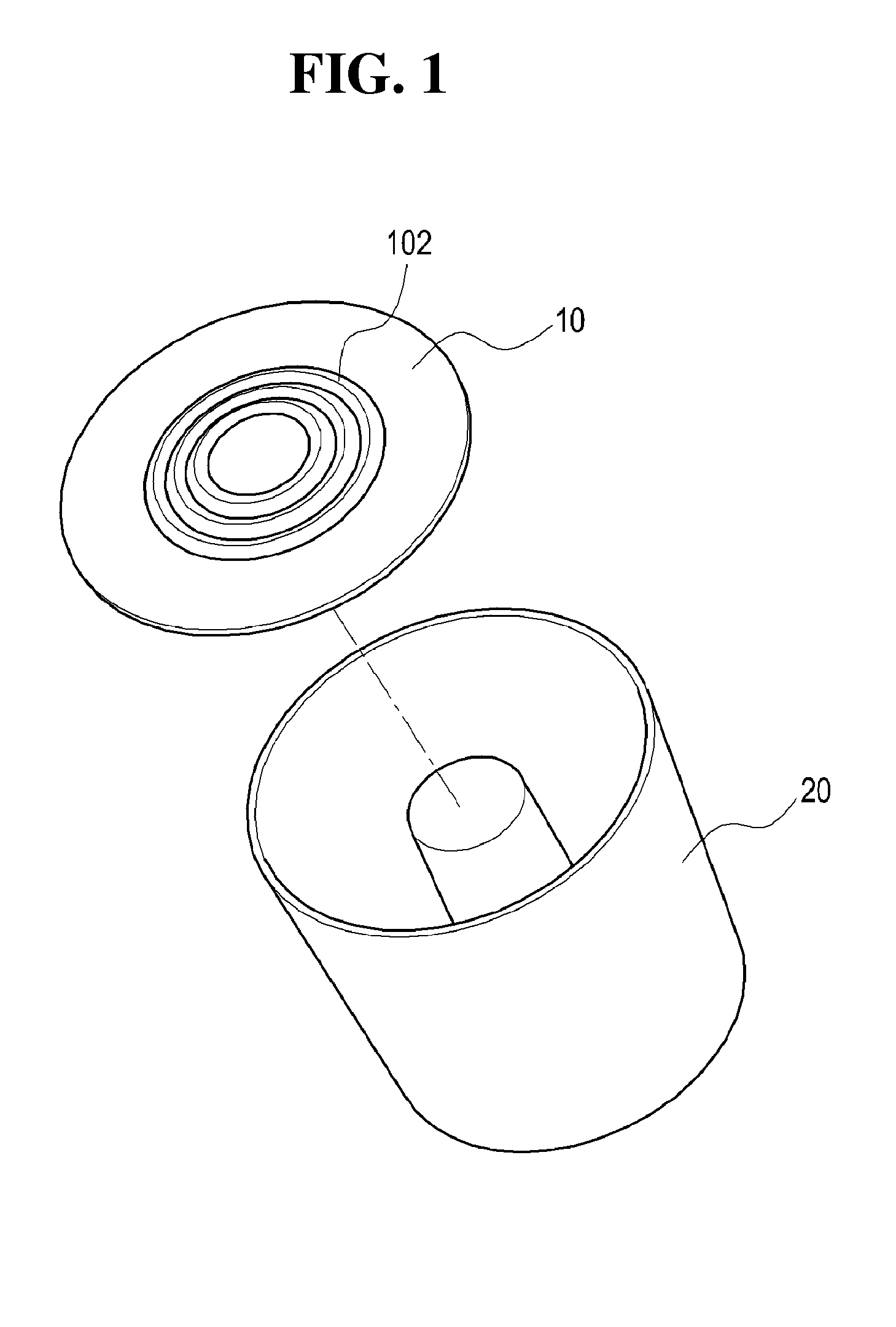
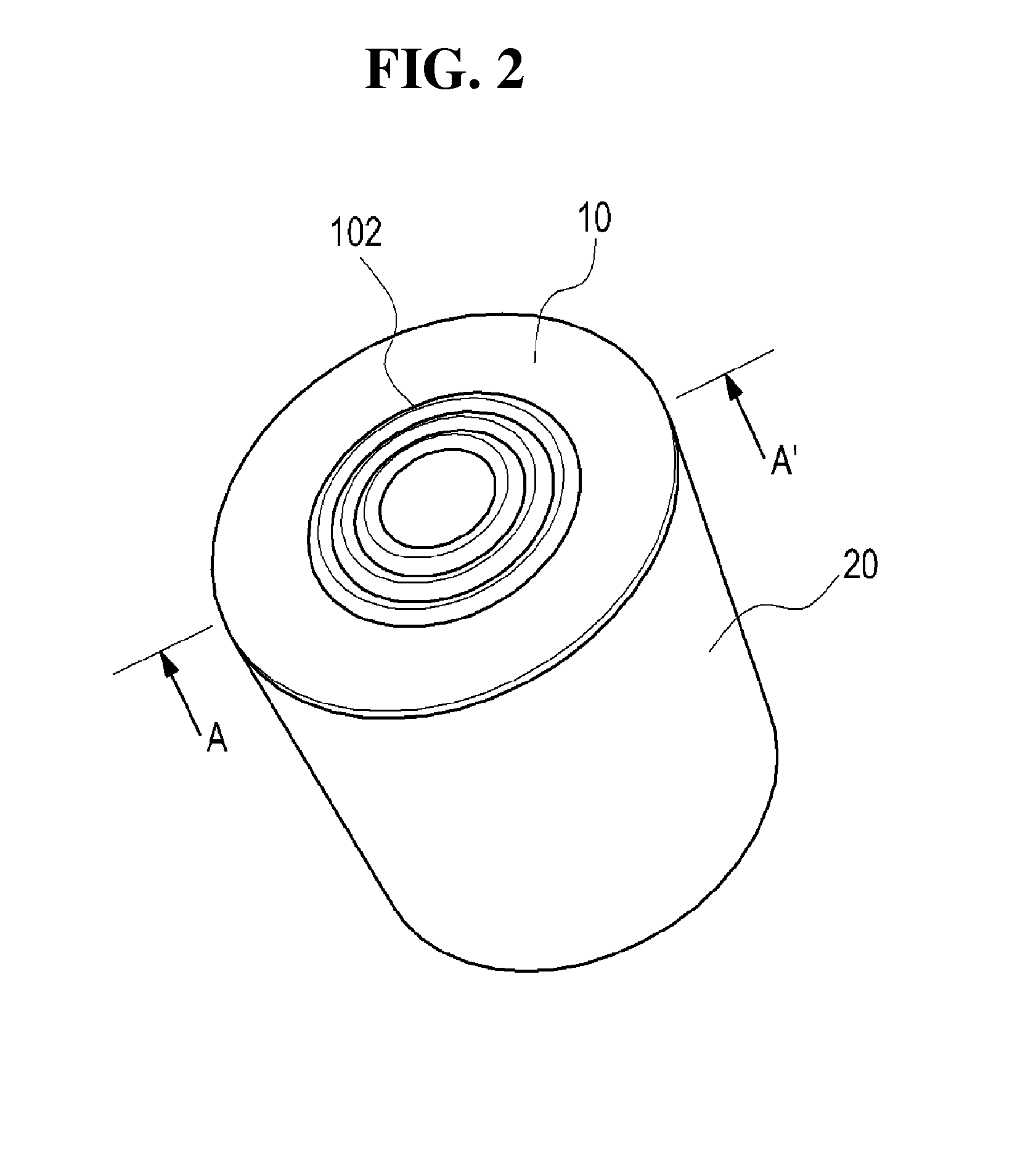
[0067]Referring to FIGS. 16 and 17, as in the other embodiments of the present invention, where a plurality of wrinkle structures 112 in which one or more curved surfaces protruding upwards and downwards are formed along a closed loop (for example, along a circle) to be used for frequency tuning at portions of the upper case 11 acting as a cover in the radio frequency filter according to the present invention, the portions of the upper case 11 corresponding to a plurality of resonance elements 21 (or protrusions) are formed or installed in the lower case.

[0068]However, unlike the other embodiments in which the side surface shapes of the curved surfaces protruding upwards and downward have a triangular curved shape, the wrinkle structure 112 of the fifth embodiment of the present invention has a rectangular curved structure. As an example, in order to form a rectangular curved structure, a plurality of substantially circular recesses 112a and 112b are alternately formed on an upper s...

seventh embodiment

[0084]In more detail, referring to FIGS. 23 and 24, as in the seventh embodiment, almost all the contour of the press portion 172 is formed by one or more slots 172a and 172b to form an entire shape. One or more connecting points a and b of the contour are connected to other portions of the upper case 17 to support the press portions 172. The press portion 172 may have a substantially long bar shape, and the connecting points a and b may be formed at opposite ends of the bar shape.

[0085]As shown in FIG. 24, if the press portion 172 is pressed during the frequency tuning operation in this structure, the connecting points a and b are extended and bent, and a central portion of the press portion 172 in the form of a bar is bent toward the resonance element 21 of the lower case for frequency tuning.

[0086]FIG. 25 is a perspective view of an upper case of a radio frequency filter having a cavity structure according to a ninth embodiment of the present invention. FIG. 26 is a cutaway secti...


PUM


Abstract

The present invention relates to a radio frequency filter having a cavity structure, comprising: a container which has a hollow inner portion and a cavity that is cut off from the outside, and a resonance element which is placed in the hollow inner portion of the container, wherein the container has a wrinkled structure for adjusting the intervals between a longitudinal front end surface of the resonance element and the inner surfaces of the container facing the longitudinal front end surface using external pressure. Thus, the invention can be further miniaturized and is lightweight, and the design of the invention enables frequency tuning without employing a coupling structure of a tuning screw and a fastening nut, thereby obtaining a convenient and simplified structure.

Description

CROSS-REFERENCE TO RELATED APPLICATIONS[0001]This application is a continuation of International Application No. PCT / KR2013 / 001518 filed on Feb. 26, 2013, which claims priority to Korean Application No. 10-2012-0019722 filed on Feb. 27, 2012 and Korean Application No. 10-2013-0006945 filed on Jan. 22, 2013, which applications are incorporated herein by reference.TECHNICAL FIELD[0002]The present invention relates to a radio signal processing apparatus used in a radio communication system, and more particularly to a radio frequency filter having a cavity structure.BACKGROUND ART[0003]A radio frequency filter having a cavity structure generally includes a plurality of accommodation spaces having a rectangular parallelepiped shape or the like, that is, a plurality of cavities through a metallic housing, and a dielectric resonance (DR) element or a resonance element having a metallic resonance rod is provided in the cavities to generate resonance of high frequency waves. In the radio fre...

Claims


Application Information

Patent Timeline
IPC IPC(8): H01P1/207
CPCH01P1/208H01P1/207H01P1/205H01P7/04H01P1/20B44B5/00H01P7/06H01P11/008H01P1/2053
Inventor PARK, NAM-SHINJEONG, DAE-SOO
Owner KMW INC
Why Eureka
Try Eureka