Method and apparatus for using gestures to control a laser tracker

a laser tracker and gesture technology, applied in the field of coordinate measuring devices, can solve the problems of limited operator's ability to control the behavior of the tracker, loss of distance information, and more complex operation of the option mod

Active Publication Date: 2014-11-06
FARO TECH INC
View PDF7 Cites 25 Cited by
  • Summary
  • Abstract
  • Description
  • Claims
  • Application Information

AI Technical Summary

Benefits of technology

[0034]In accordance with an embodiment of the invention, a method for communicating, from a user to a laser tracker, a way to control operation of the laser tracker is provided. The method includes the with steps of: providing the laser tracker having a structure rotatable about a first axis and a second axis, a first light source that launches a first light beam from the structure, a distance meter, a first angular encoder that measures a first angle of rotation about the first axis, a second angular encoder that measures a second angle of rotation about the second axis, and a processor; providing a projector and a first camera; providing a rule of correspondence between each of a plurality of commands and each of a plurality of gestures, each gesture from among the plurality of gestures including a spatial configuration of a first body part of the user relative to a second body part of the user, the rule of correspondence based at least in part on the spatial configuration; performing a first gesture from among the plurality of gestures, the first gesture corresponding to a first command; projecting from the projector a second light onto the body, the second light being a two-dimensional pattern of light; reflecting the second light from the body as a third light; capturing a portion of the third light with the first camera to obtain a digital representation of the portion of the third light; determining the first command based at least in part on processing the digital representation according to the rule of correspondence; and executing the first command with the laser tracker.

Problems solved by technology

If the beam is broken during the measurement, the number of counts cannot be accurately known, causing the distance information to be lost.
Some option modes are slightly more complex in their operation.
The element common to the tracker actions described above is that the operator is limited in his ability to control the behavior of the tracker.
However, once the option modes have been selected by the user, the behavior of the tracker is established and cannot be changed unless the operator returns to the computer console.
In either case, the operator is limited in his ability to control the tracker and the data collected by the tracker.
However, it is not easy for a single operator to perform both of these measurement functions because the computer is usually remotely located from the measurement location.
Various methods have been tried to get around this limitation, but none is completely satisfactory.
However, this is an inefficient use of operator and instrument time.
This is labor intensive and an expensive method.
Further, verbal communication over large distances can be a problem.
However, remote controls have several limitations.
Many facilities do not allow the use of remote controls for safety or security reasons.
Even if remote controls are allowed, interference among wireless channels may be an issue.
Some remote control signals do not reach the full range of the laser tracker.
In some situations, such as working from a ladder, the second hand may not be free to operate the remote control.
Some facilities do not allow cell phones to be used, and cell phones may not be available in rural areas.
However, this method has limitations similar to a cell phone.
It might be possible to adapt this method to give commands to a laser tracker, but it is not usually very easy to find a suitable surface upon which to project the pointer beam pattern.
Such a method is not suitable for use with a laser tracker, where it is advantageous to use a small target not tethered to a large control pad.
However, this method does not offer the ability to send general purpose commands to a laser tracker.
This type of retroreflector is complex and expensive.
It degrades the quality of the retroreflected light because of the switch (which might be a ferro-electric light crystal material) and because of the truncated apex.
Also, the light returned to a laser tracker is already modulated for use in measuring the ADM beam, and switching the light on and off would be a problem, not only for the ADM, but also for the tracker interferometer and position detector.
Such a method is not suitable for use with a laser tracker, where it is advantageous to use a small target not tethered to a large control pad.
Also the method of identifying the retroreflector target of interest is complicated and expensive.

Method used


Image

  • Method and apparatus for using gestures to control a laser tracker
  • Method and apparatus for using gestures to control a laser tracker
  • Method and apparatus for using gestures to control a laser tracker

Examples


Embodiment Construction

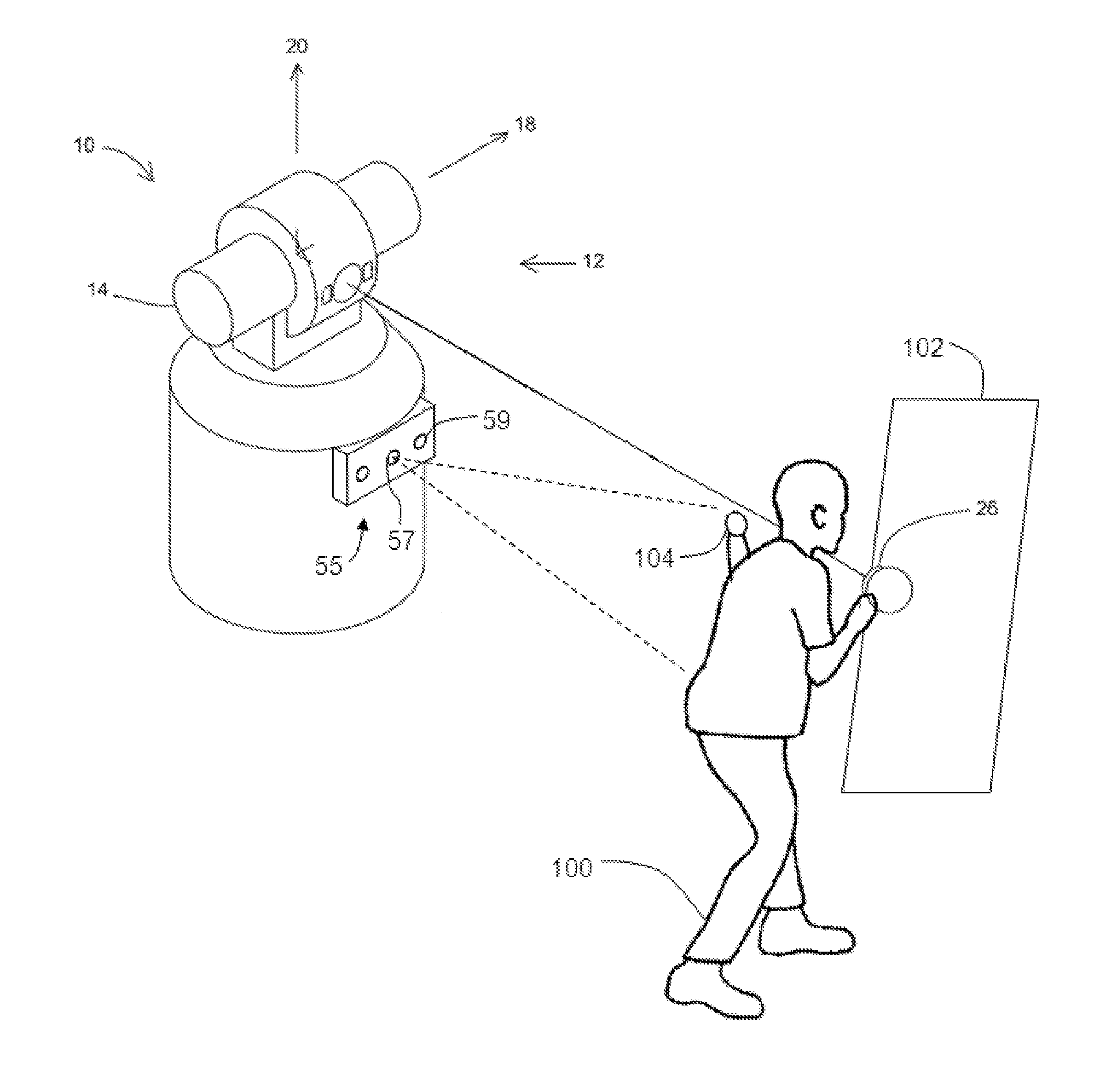
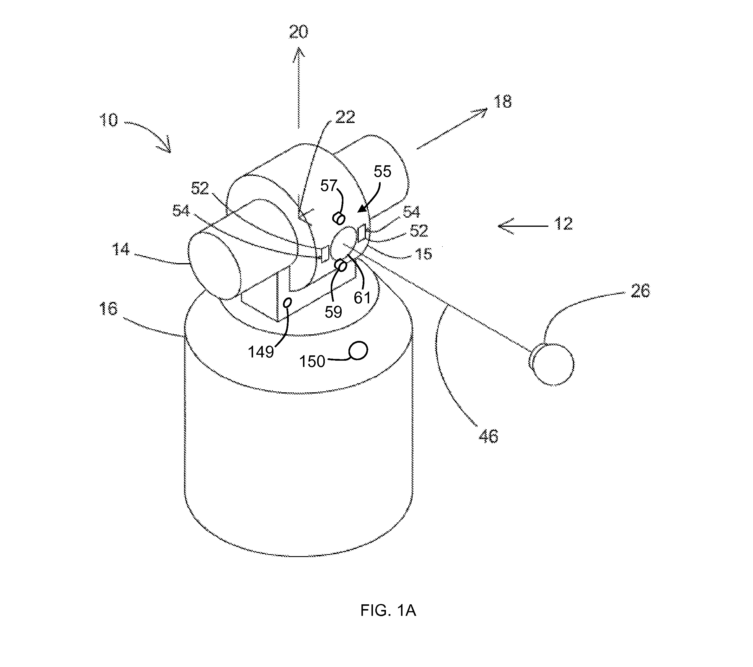
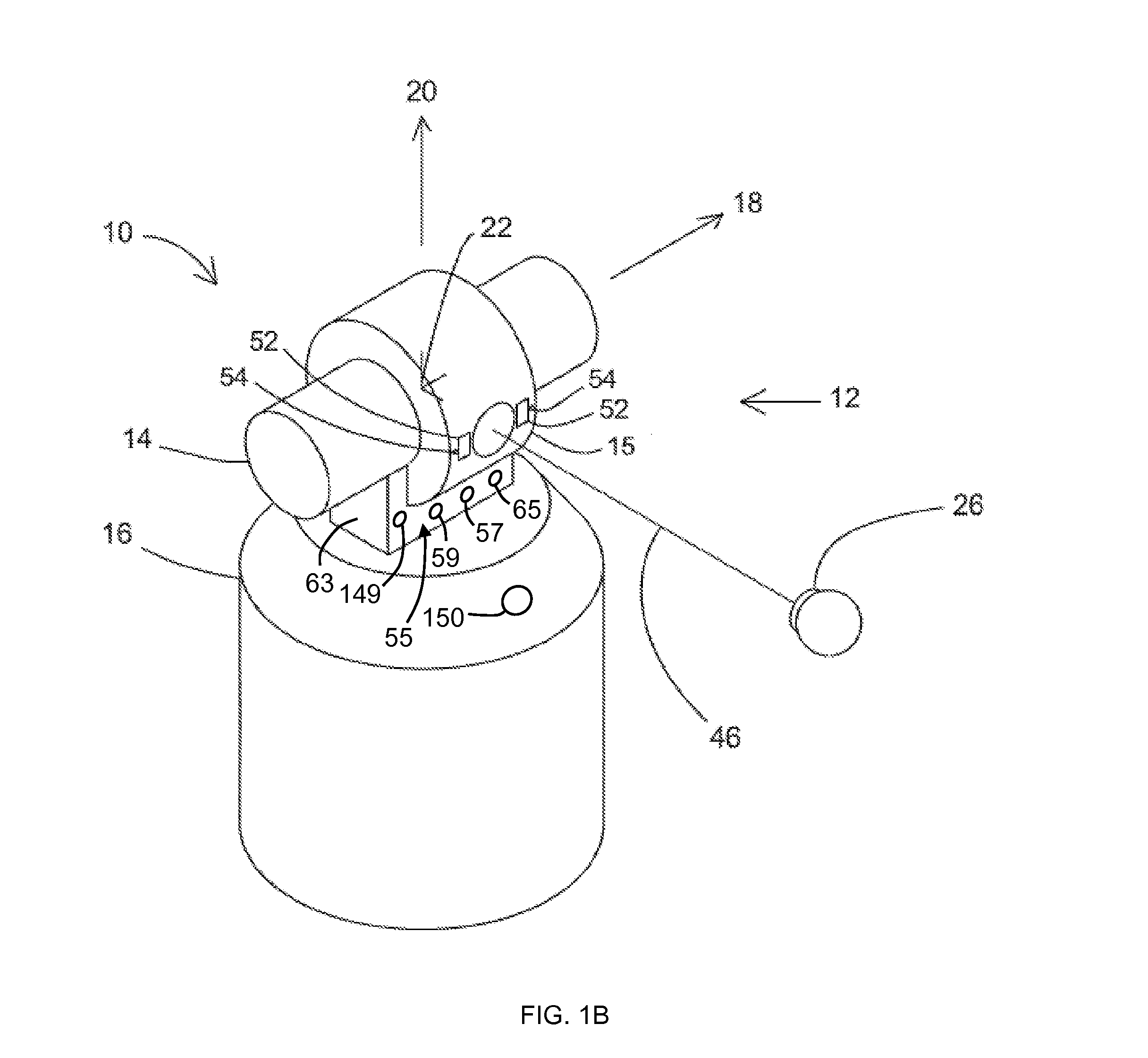
[0053]An exemplary laser tracker 10 is illustrated in FIG. 1. An exemplary gimbaled beam-steering mechanism 12 of laser tracker 10 comprises zenith carriage 14 mounted on azimuth base 16 and rotated about azimuth axis 20. Payload 15 is mounted on zenith carriage 14 and rotated about zenith axis 18. Zenith mechanical rotation axis 18 and azimuth mechanical rotation axis 20 intersect orthogonally, internally to tracker 10, at gimbal point 22, which is typically the origin for distance measurements. Laser beam 46 virtually passes through gimbal point 22 and is pointed orthogonal to zenith axis 18. In other words, laser beam 46 is in the plane normal to zenith axis 18. Laser beam 46 is pointed in the desired direction by motors within the tracker (not shown) that rotate payload 15 about zenith axis 18 and azimuth axis 20. Zenith and azimuth angular encoders, internal to the tracker (not shown), are coupled to zenith mechanical axis 18 and azimuth mechanical axis 20 and indicate, to high...


PUM


Abstract

A method and system are provided for controlling a laser tracker remotely from the laser tracker through gestures performed by a user. The method includes providing a rule of correspondence between each of a plurality of commands and each of a plurality of user gestures. A gesture is performed by the user with the user's body that corresponds to one of the plurality of user gestures. The gesture performed by the user is detected. The gesture recognition engine determines a first command from one of the plurality of commands that correspond with the detected gesture. Then the first command is executed with the laser tracker.

Description

CROSS REFERENCE TO RELATED APPLICATIONS[0001]The present application is a Nonprovisional application of U.S. Provisional Application Ser. No. 61 / 818,208 filed on May 1, 2013 entitled “Method and Apparatus for Using Gestures to Control a Laser Tracker,” the contents of which are incorporated by reference herein.BACKGROUND OF THE INVENTION[0002]The present disclosure relates to a coordinate measuring device. One set of coordinate measurement devices belongs to a class of instruments that measure the three-dimensional (3D) coordinates of a point by sending a laser beam to the point, where it is intercepted by a retroreflector target. The instrument finds the coordinates of the point by measuring the distance and the two angles to the target. The distance is measured with a distance-measuring device such as an absolute distance meter (ADM) or an interferometer. The angles are measured with an angle-measuring device such as an angular encoder. A gimbaled beam-steering mechanism within th...

Claims


Application Information

Patent Timeline
Patent Type & Authority Applications(United States)
IPC IPC(8): G01B11/00G06F3/01G01B11/14G01S17/86
CPCG01B11/002G06F3/017G01B11/14G01C15/002G01S17/66G06F3/015G06T7/30G06T7/12G06T7/174G06T7/194G01S17/86G06V40/20G06V40/28G01S3/786G06T2207/20224G06T2207/30196G06T7/254G06T2207/10016
Inventor BRIDGES, ROBERT E.PARKER, DAVID H.FLETCHER, KELLEYPEASE, GREGORY D.
Owner FARO TECH INC
Why Eureka
Try Eureka