Method for vapor-cleaning object to be cleaned and device therefor

a technology for cleaning objects and cleaning vapor, which is applied in the direction of household cleaners, vacuum cleaners, tableware washing/rinsing machines, etc., can solve the problems of increasing cleaning costs, increasing cleaning solvent consumption, and rapidly reducing vapor levels, so as to facilitate cleaning vapor management

Inactive Publication Date: 2014-11-13
JAPAN FIELD
View PDF4 Cites 2 Cited by
  • Summary
  • Abstract
  • Description
  • Claims
  • Application Information

AI Technical Summary

Benefits of technology

[0008]Because, as described above, an outlet is provided in a cover plate, through which cleaning vapor flows out into an overhead ordinary pressure working chamber, and because the cleaning vapor flows out only from the outlet into the working chamber and the cleaning vapor does not flow to the entire interior of the working chamber, the present invention makes the management of cleaning vapor very easy. That is to say, when not vapor cleaning an object to be cleaned, the vapor that has flowed out from the outlet can be condensed by a condensation unit at a low position in the working chamber, so that there will be very little pushing up of air in the working chamber, which would result in discharge to the exterior of the working chamber.
[0009]Furthermore, when an object to be cleaned is vapor cleaned, a tubular cleaning tube is arranged on the top face of the cover plate, at the outer periphery of the outlet, so that the cleaning vapor can accumulate at the interior of this tubular cleaning tube. The volume of air that is pushed up by this cleaning vapor is approximately equal to the volume of this cleaning tube. Consequently, while conventionally all of the air in the working chamber was pushed out to the exterior, by causing the volume of this cleaning tube to be the minimum necessary for cleaning the object to be cleaned, only an amount of air corresponding to the volume of the cleaning tube will be pushed out to the exterior, which allows for a great reduction as compared to that which was conventional.
[0010]Furthermore, when an object to be cleaned in placed in the cleaning tube and vapor cleaned, the volume by which the cleaning vapor is reduced as a result of condensation by the object to be cleaned, will likewise correspond to the volume of the cleaning tube, and thus little air will flow into the cleaning chamber from the exterior. Furthermore, cleaning vapor that overflows from the cleaning tube can be condensed by the condensation unit at a low position in the working chamber, so that there will be very little influence on pushing of the air in the working chamber upwards.

Problems solved by technology

Consequently, air containing the cleaning solvent is dispersed to the exterior, which not only has a great environmental impact, but increases the consumption of cleaning solvent, which results in increased cleaning costs.
Furthermore, when the object to be cleaned is placed in the working chamber that has been filled with cleaning vapor, the cleaning vapor is condensed by the object to be cleaned, which rapidly decreases the vapor level.
There were problems in so much as, as a result of repeating this, the environmental impact increased and the consumption of cleaning solvent increased.
Furthermore, 1,1,1-trichloroethane and Freon 113, which are ozone depleting substances, have been banned, and because replacement cleaning solvents are more expensive than the cleaning solvents that were conventionally used, the consumption of cleaning solvents constitutes a serious problem.
Furthermore, with a view to solving these problems, methods are known in which vapor cleaning is performed within a sealed vacuum tank, but there are disadvantages to this in that the equipment is expensive.

Method used


Image

  • Method for vapor-cleaning object to be cleaned and device therefor
  • Method for vapor-cleaning object to be cleaned and device therefor
  • Method for vapor-cleaning object to be cleaned and device therefor

Examples


working example 2

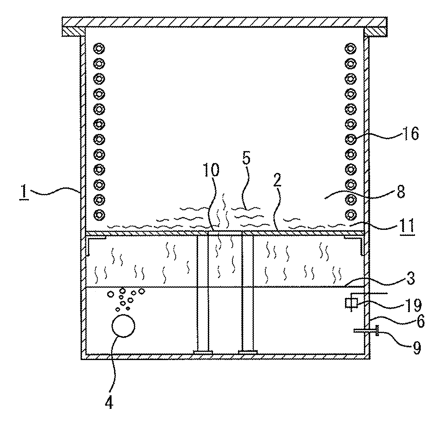
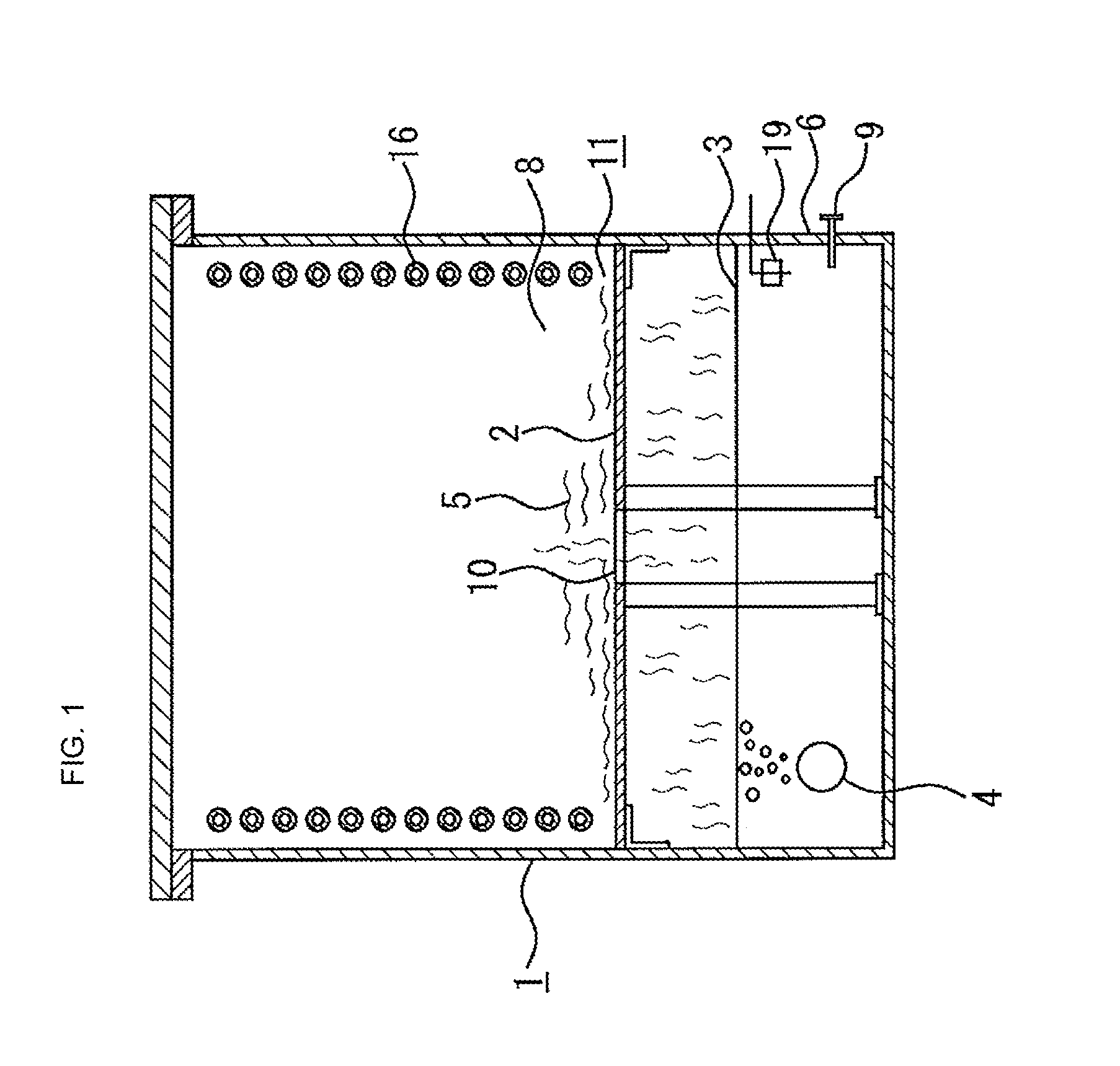
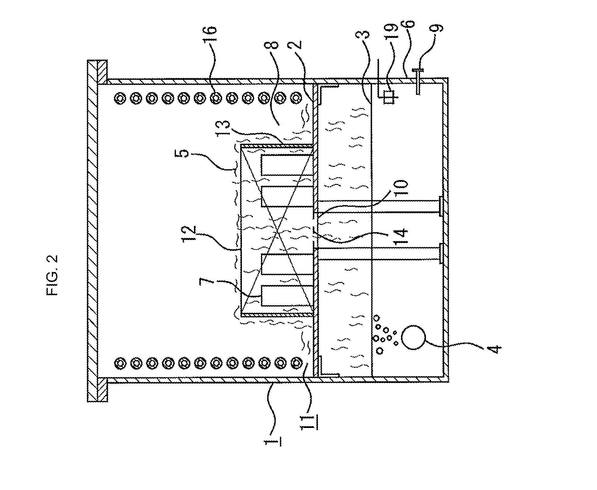
[0025]In embodiment 1 described above, the configuration is such that the condensation unit (11) is provided on the inner face of the working chamber (8) in communication with the top face of the cover plate (2), and a portion thereof is arranged closer to the lower cover plate (2) than the top of the cleaning tube (12). However, in Embodiment 2, as shown in FIG. 3 and FIG. 4, the configuration is such that the condensation unit (11) communicates with the working chamber (8) via a communication opening (15) provided at the top face of the cover plate (2) and at a horizontally lateral part thereof. The condensation unit (11) in this Embodiment 2 is configured such that cooled cleaning solvent (3) fills the interior of a cooling tank (17), at the inner periphery of which a cooling pipe (16) is arranged, through which cooling liquid passes. Here, when a vapor cleaning is not performed, the cleaning vapor (5) that flows out from the outlet (10) is introduced via the communication openin...

working example 3

[0029]In Embodiments 1 and 2 described above, the vapor generation unit (6) was provided below the vapor cleaning tank (1), which is vertically divided by the cover plate (2), this vapor generation unit (6) was filled with cleaning solvent (3), and this cleaning solvent (3) was heated by the heater (4), so as to generate cleaning vapor (5). However, as shown in FIG. 5 and FIG. 6, in Embodiment 3, the vapor generation unit (6) is configured entirely separately from the vapor cleaning tank (1). The bottom of this vapor generation unit (6) is filled with cleaning solvent (3) and this cleaning solvent (3) is heated with a heater (4) so as to generate cleaning vapor (5). Additionally, an accumulation unit (28) for the cleaning vapor (5) is provided above the cleaning solvent (3), and a condensation chamber (31) is arranged above this accumulation unit (28), with a separator plate (30) therebetween. At the inner periphery of this condensation chamber (31), a cooling pipe (16), through whi...


PUM


Abstract

When an object to be cleaned is vapor cleaned in the prior art, a tubular cleaning tube is arranged on the top face of the cover plate, at the outer periphery of the outlet, so that the cleaning vapor can accumulate, allowing very little pushing out the air in the working chamber. In the present invention, an outlet is provided in a cover plate through which cleaning vapor flows out into an ordinary pressure working chamber thereabove; condensation of this outflowing cleaning vapor at a low position in the ordinary pressure working chamber is made possible by a condensation unit; and a tubular cleaning tube is arranged at the outer periphery of the outlet on the top face of a cover plate, whereby the cleaning vapor rises up in the cleaning tube so that an object to be cleaned can be vapor cleaned by receiving it in this cleaning tube.

Description

TECHNICAL FIELD[0001]The present invention relates to a method of vapor cleaning an object to be cleaned performed in an ordinary pressure environment and a device for the same, an object thereof being the prevention of dispersion of cleaning solvent into the atmosphere, so as to reduce the environmental impact, and so as to lower the cost of vapor cleaning an object to be cleaned by reducing the amount of cleaning solvent consumed when vapor cleaning the object to be cleaned.BACKGROUND ART[0002]Conventionally, a method of vapor cleaning an object to be cleaned in an ordinary pressure environment is known in which a cleaning solvent loaded in an ordinary pressure vapor generator is heated so as to generate cleaning vapor that fills a working chamber thereabove, an object to be cleaned is brought into contact with the cleaning vapor in this working chamber, and vapor cleaning is performed, as set forth in Patent Document 1. In this conventional method, a condensation unit is configur...

Claims


Application Information

Patent Timeline
Patent Type & Authority Applications(United States)
IPC IPC(8): B08B3/00
CPCB08B3/00B08B2230/01
Inventor UCHINO, MASATOSHIUCHINO, MASAHIDE
Owner JAPAN FIELD
Why Eureka
Try Eureka