Contactless power transmission device

a technology of power transmission device and contactless, which is applied in the direction of charging station, electric vehicle charging technology, transportation and packaging, etc., can solve the problem of low transmission efficiency of contactless power transmission, and achieve the effect of lowering transmission efficiency

Inactive Publication Date: 2014-11-13
TOYOTA IND CORP
View PDF3 Cites 15 Cited by
  • Summary
  • Abstract
  • Description
  • Claims
  • Application Information

AI Technical Summary

Benefits of technology

[0004]When the load on a power transmission line changes in accordance with the distance between the primary side resonance coil and the secondary side resonance coil or the state of charge of the vehicle battery, AC...

Problems solved by technology

This may lower the transmission efficiency during contactless power transmissi...

Method used


Image

  • Contactless power transmission device
  • Contactless power transmission device
  • Contactless power transmission device

Examples


first embodiment

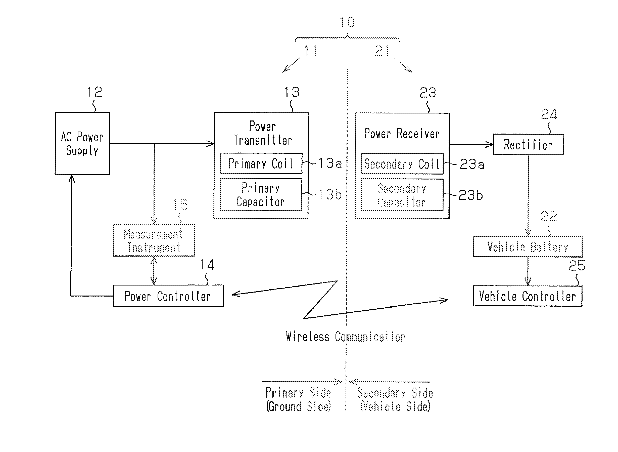
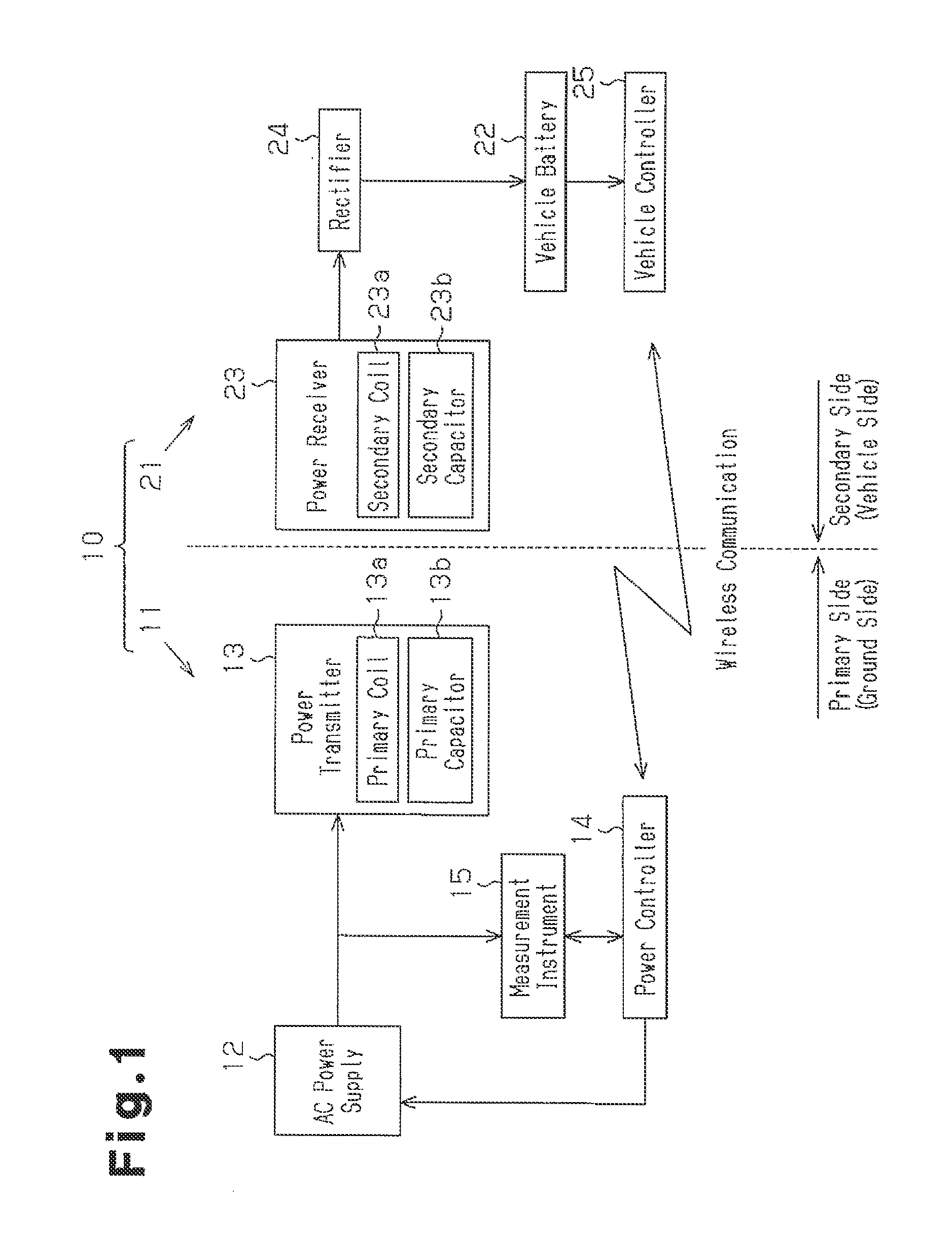
[0018]A first embodiment of a contactless power transmission device according to the present invention will now be described with reference to FIG. 1.

[0019]As shown in FIG. 1, the contactless power transmission device 10 includes a ground device 11, which is arranged on ground, and a vehicle device 21, which is installed in a vehicle. The ground device 11 corresponds to a primary side (power supplying side) structure, and the vehicle device 21 corresponds to a secondary side (power receiving side) structure.

[0020]The ground device 11 includes an AC power supply 12, which is capable of supplying AC power having a predetermined frequency (e.g., 10 kHz to 10 MHz) , and a power transmitter 13. The power transmitter 13 is electrically connected to the AC power supply 12, and the power transmitter 13 is supplied with AC power from the AC power supply 12. The vehicle device 21 includes a vehicle battery 22 and a power receiver 23, which is capable of receiving AC power from the power trans...

second embodiment

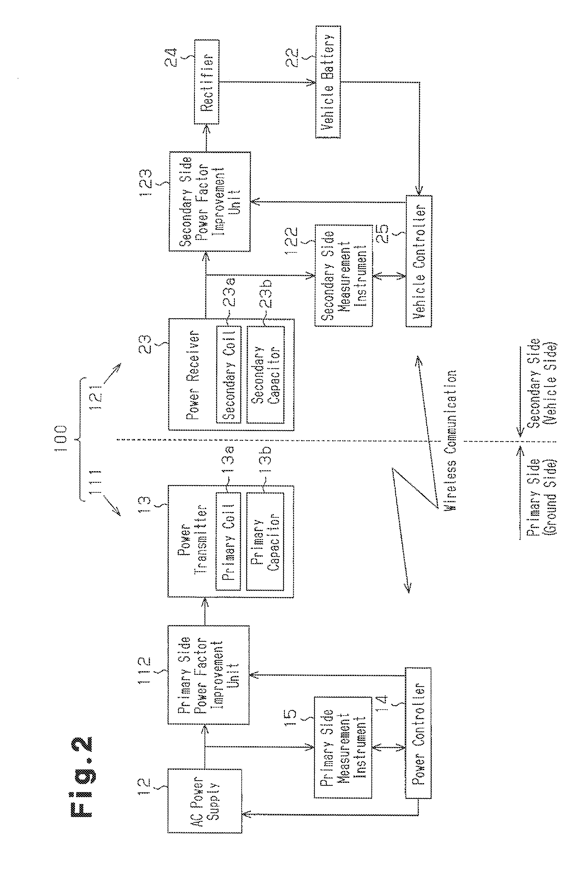
[0051]Referring to FIG. 2, a contactless power transmission device 100 of the present embodiment differs from the contactless power transmission device 10 of the first embodiment in that a configuration for calculating the power factor is employed in both of the primary side (ground side) and the secondary side (vehicle side) and in that a configuration for improving each power factor is employed. These points will be described hereafter. Same reference numerals are given to those components that are the same as the corresponding components of the first embodiment. Such components will not be described.

[0052]A vehicle device 121 includes a measurement instrument 122 that measures the apparent power and the effective power input to a load from the output portion of the power receiver 23 (secondary coil 23a) to the vehicle battery 22. To distinguish the measurement instrument 122 from the measurement instrument, of a ground device 111 (measurement instrument 15 of the first embodiment...


PUM


Abstract

A contactless power transmission device is provided with an AC power source, a primary coil, a secondary coil, an electric component and a power factor calculation unit. The primary coil is supplied with AC power from the AC power source. The secondary coil is allowed to receive AC power from the primary coil. The electric component is supplied with the AC power that is received by the secondary coil. The power factor calculation unit calculates at least either the power factor with respect to the load from the output of the AC power source to the electric component, or the power factor with respect to the load from the output of the secondary coil to the electric component.

Description

TECHNICAL FIELD[0001]The present invention relates to a contactless power transmission device.BACKGROUND ART[0002]A contactless power transmission device that uses, for example, magnetic field resonance instead of a power supply cord or a power transmission cable is known in the prior art. For example, in patent document 1, a power supplying device includes an AC power supply and a primary side resonance coil, which is supplied with AC power from the AC power supply. The vehicle includes a secondary side resonance coil, which is capable of performing magnetic field resonance with the primary side resonance coil, and a vehicle battery. When the resonance coils undergo magnetic field resonance, AC power is transmitted to the secondary side resonance coil. A rectifier, which is arranged in the vehicle, rectifies the AC power, which is input to the vehicle battery.PRIOR ART DOCUMENTPatent Document[0003]Patent Document 1: Japanese Laid-Open Patent Publication No. 2009-106136SUMMARY OF TH...

Claims


Application Information

Patent Timeline
IPC IPC(8): B60L11/18H02J5/00H02J7/00
CPCB60L11/182H02J5/005B60L2210/30B60L2210/40Y02T90/14Y04S30/14Y02T10/7072B60L53/36B60L53/65B60L53/126B60L53/124B60L53/122H02J2310/48H02J7/00034Y02T10/72Y02T90/12Y02T90/167Y02T10/70H02J50/80H02J50/90H02J50/12Y02T90/16B60L53/12
Inventor MATSUKURA, KEISUKEKONDO, TADASHI
Owner TOYOTA IND CORP
Why Eureka
Try Eureka