Monolithic Heat Exchanger and Apparatus and Methods for Hydrogenation of a Halosilane

a heat exchanger and monolithic technology, applied in the direction of heat exchange apparatus safety devices, indirect heat exchangers, lighting and heating apparatus, etc., can solve the problems of large base plate, large loss of primary raw materials silicon and chlorine, and large loss of primary raw materials, etc., to reduce the temperature of component parts and increase the area available for convective heat transfer

Active Publication Date: 2014-11-13
HAZELTINE BRUCE
View PDF2 Cites 3 Cited by
  • Summary
  • Abstract
  • Description
  • Claims
  • Application Information

AI Technical Summary

Benefits of technology

[0041]FIG. 19 is a schematic cross sectional end view of the susceptor, heater and baffle showing fins on the outside diameter of a susceptor to increase area available for convective heat transfer and thus reduce the temperature of component parts.

Problems solved by technology

In most cases, the multiple block designs are due to size limitations of the starting monolithic materials.
If STC could not be recycled, there would be a huge loss of the primary raw materials silicon and chlorine and a cost for disposal of the byproduct STC.
This equipment has a number of problems.
Furthermore, the retrofitted CVD reactors have a large, heavy baseplate, that is expensive and makes it inconvenient to add heat exchanger equipment for recovery of heat.
Moreover, the heated graphite rods in a retrofitted CVD reactor require a large number of electrical connections.
Every connection is a potential source of rod failure.
Every baseplate penetration represents risks for electrical ground faults.
Furthermore, CVD reactors have a high radiation heat loss to the shell, wasting large amounts of energy.
Cheaper insulating materials do not exhibit an adequate lifetime due to reaction with reactant gases at the high temperatures involved.
As a result of the size and expensive nature of the materials needed, insulation on a Siemens style hydrogenation reactor is very expensive.
Key components of the hydrogenation reactor have limited lifetimes and must be replaced at regular intervals—including the heating elements, the electrical connections, the insulation, and components of the heat exchanger.
However, such purpose-built systems are not widely used, and are not yet commercially available.
This design appears challenging to fabricate and limited in scalability and heat transfer efficiency as the gas must flow from a large to a small diameter.

Method used


Image

  • Monolithic Heat Exchanger and Apparatus and Methods for Hydrogenation of a Halosilane
  • Monolithic Heat Exchanger and Apparatus and Methods for Hydrogenation of a Halosilane
  • Monolithic Heat Exchanger and Apparatus and Methods for Hydrogenation of a Halosilane

Examples


constructive examples

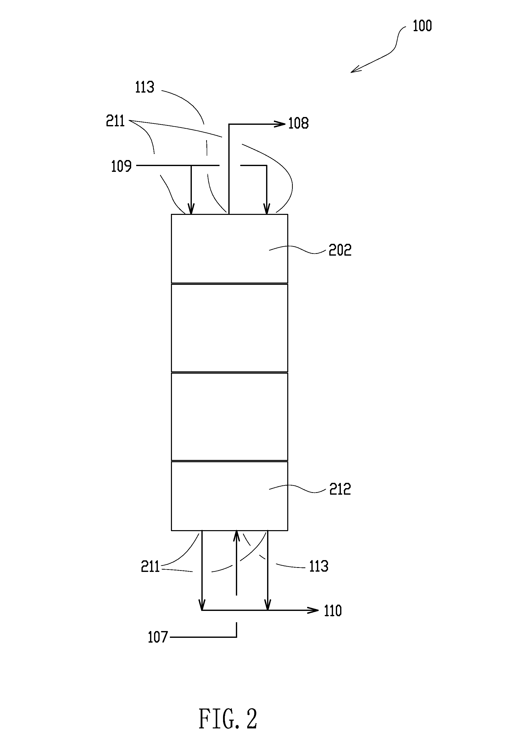
[0107]Standard engineering techniques known to those skilled in the art were used to compare the thermal and hydraulic performance of the counter-current heat exchanger of this invention to a cylindrical cross flow heat exchanger useful in an STC hydrogenation reactor. Heat transfer coefficients can be estimated as flow through a tube using equations such as the Seider Tate equation. Hydraulic performance can be estimated as presented by the Serghides's solution and the Darcy equation. Heat transfer through the solid portion of the heat exchanger is estimated as concentric circular rings using techniques known to those skilled in the art. Taking a cross flow heat exchanger as that found in FIG. 2 of the Fahrenbruck U.S. Patent Application Publication US2012 / 0328503 A1, which is believed representative of the performance achievable in a cross flow heat exchanger, was used for comparison. It assumes the heat exchanger block referenced in the constructive example is 610 mm diameter by ...


PUM


Abstract

A counter current heat exchanger amenable to fabrication from monolithic materials and particularly useful in corrosive and high temperature environments is described. The heat exchanger uses multiple series of holes bored axially through a monolithic material. Axial holes are bored in adjacent flow paths arranged in closely spaced concentric rings. In operation, counter current flow and heat transfer occurs between multiple adjacent axial flow paths. The heat exchanger design is scaleable over a wide range and particularly useful in reactors for the hydrogenation of halosilanes also using cylindrical heating elements. The design enables a small overall reactor size for a given capacity.

Description

CROSS-REFERENCE TO RELATED APPLICATIONS[0001]This application claims the benefits of U.S. Provisional Application No. 61 / 820,607 filed May 7, 2013, the disclosure of which is hereby incorporated by reference in its entirety including all figures, tables, and drawings.STATEMENT REGARDING FEDERALLY SPONSORED RESEARCH OR DEVELOPMENT[0002]Not applicable.REFERENCE TO SEQUENCE LISTING, A TABLE, OR A COMPUTER PROGRAM LISTING COMPACT DISC APPENDIX[0003]Not applicable.FIELD OF THE INVENTION[0004]This invention relates generally to a heat transfer apparatus made using monolithic materials such as graphite and methods for hydrogenation of a halosilane. More particularly, in certain embodiments, the invention relates to an apparatus and methods for conversion of silicon tetrachloride (STC) to trichlorosilane (TCS).BACKGROUND OF THE INVENTION[0005]In corrosive and high temperature environments, heat exchangers made of monolithic materials such as graphite are routinely used in the chemical indus...

Claims


Application Information

Patent Timeline
Patent Type & Authority Applications(United States)
IPC IPC(8): B01J19/24F28D7/10
CPCB01J19/24F28D7/10B01J2219/2408B01J2219/2409B01J19/2485B01J2219/2416B01J2219/2419B01J2219/2433C01B33/107F28F7/02F28F21/02F28F2265/26B01J12/005
Inventor HAZELTINE, BRUCE
Owner HAZELTINE BRUCE
Why Eureka
Try Eureka