Organometallic complex, light-emitting element, light-emitting device, electronic appliance, and lighting device

Inactive Publication Date: 2014-11-20
SEMICON ENERGY LAB CO LTD
View PDF1 Cites 16 Cited by
  • Summary
  • Abstract
  • Description
  • Claims
  • Application Information

AI Technical Summary

Benefits of technology

[0030]According to one embodiment of the present invention, a light-emitting element that includes a phosphorescent organometallic complex can be provided. According to one embodiment of the pre

Problems solved by technology

This feature is difficult to obtain with point light sources typified by inca

Method used


Image

  • Organometallic complex, light-emitting element, light-emitting device, electronic appliance, and lighting device
  • Organometallic complex, light-emitting element, light-emitting device, electronic appliance, and lighting device
  • Organometallic complex, light-emitting element, light-emitting device, electronic appliance, and lighting device

Examples


embodiment 1

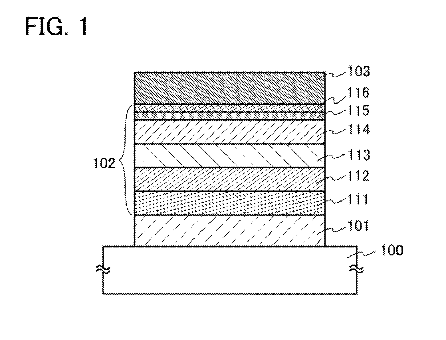
[0064]In this embodiment, a light-emitting element that includes, between a pair of electrodes, an EL layer containing an organometallic complex is described with reference to FIG. 1.

[0065]In a light-emitting element described in this embodiment, as illustrated in FIG. 1, an EL layer 102 including a light-emitting layer 113 is provided between a pair of electrodes (a first electrode 101 and a second electrode 103), and the EL layer 102 includes a hole-injection layer 111, a hole-transport layer 112, an electron-transport layer 114, an electron-injection layer 115, a charge-generation layer 116, and the like in addition to the light-emitting layer 113. Note that in this embodiment, the first electrode 101 is used as an anode and the second electrode 103 is used as a cathode. The first electrode 101 is formed over a substrate 100. The light-emitting layer 113 contains an organometallic complex of one embodiment of the present invention.

[0066]By application of voltage to such a light-e...

embodiment 2

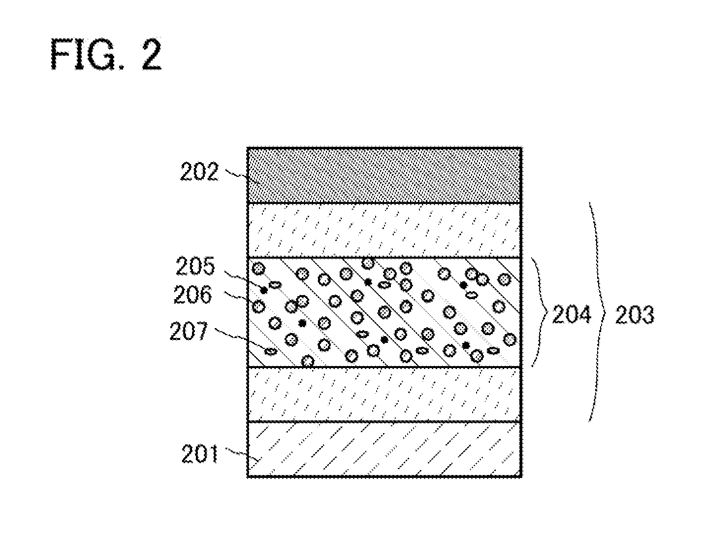
[0123]In this embodiment, a light-emitting element that includes, between a pair of electrodes, an EL layer including a light-emitting layer containing an organometallic complex of one embodiment of the present invention and two or more kinds of organic compounds is described with reference to FIG. 2.

[0124]A light-emitting element described in this embodiment includes an EL layer 203 between a pair of electrodes (a first electrode 201 and a second electrode 202) as illustrated in FIG. 2. Note that the EL layer 203 includes at least a light-emitting layer 204 and may include a hole-injection layer, a hole-transport layer, an electron-transport layer, an electron-injection layer, a charge-generation layer, and the like. Note that in FIG. 2, the above-described hole-injection layer, hole-transport layer, electron-transport layer, electron-injection layer, and charge-generation layer, and the like can be provided as appropriate between the first electrode 201 and the EL layer 203 and be...

embodiment 3

[0138]In this embodiment, as one embodiment of the present invention, a light-emitting element (hereinafter referred to as tandem light-emitting element) in which a charge-generation layer is provided between a plurality of EL layers is described.

[0139]A light-emitting element described in this embodiment is a tandem light-emitting element including a plurality of EL layers (a first EL layer 302(1) and a second EL layer 302(2)) between a pair of electrodes (a first electrode 301 and a second electrode 304) as illustrated in FIG. 3A.

[0140]In this embodiment, the first electrode 301 functions as an anode, and the second electrode 304 functions as a cathode. Note that the first electrode 301 and the second electrode 304 can have structures similar to those described in Embodiment 1. In addition, although the plurality of EL layers (the first EL layer 302(1) and the second EL layer 302(2)) may have structures similar to those described in Embodiment 1 or 2, any of the EL layers may have...


PUM


Abstract

A light-emitting element including a phosphorescent organometallic complex is provided. The organometallic complex emits phosphorescence in the yellow green to orange wavelength range and has high emission efficiency and high reliability. Thus, the organometallic complex that exhibits phosphorescence is provided. The organometallic complex, in which nitrogen at the 3-position of a pyrimidine ring is coordinated to a metal, a carbazole skeleton is bonded to the 4-position of the pyrimidine ring, and the carbazole skeleton is bonded to the metal, is used as an emission center. The metal is preferably a Group 9 element or a Group 10 element, more preferably iridium.

Description

BACKGROUND OF THE INVENTION[0001]1. Field of the Invention[0002]The present invention relates to an organometallic complex, a light-emitting element, a light-emitting device, an electronic appliance, and a lighting device.[0003]2. Description of the Related Art[0004]In recent years, research and development have been extensively conducted on light-emitting elements using electroluminescence (EL). In the basic structure of such a light-emitting element, a layer containing a light-emitting substance is interposed between a pair of electrodes. By applying voltage to this element, light emission from the light-emitting substance can be obtained.[0005]The light-emitting element is a self-luminous element and thus has advantages over a liquid crystal display element, such as high visibility of the pixels and no need of backlight, and is considered to be suitable as a flat panel display element. Another major advantage of the light-emitting element is that it can be thin and lightweight. B...

Claims


Application Information

Patent Timeline
IPC IPC(8): H01L51/00
CPCH01L51/0085C07F15/0033C09K11/06C09K2211/1007C09K2211/1029C09K2211/1044C09K2211/185H10K85/636H10K85/633H10K85/6572H10K85/342H10K50/11H10K2101/10
Inventor INOUE, HIDEKOYAMAGUCHI, TOMOYASEO, HIROMITAKAHASHI, TATSUYOSHISEO, SATOSHI
Owner SEMICON ENERGY LAB CO LTD
Why Eureka
Try Eureka