

Material for organic electroluminescence device and organic electroluminescence device
- Summary
- Abstract
- Description
- Claims
- Application Information
AI Technical Summary
Benefits of technology
Problems solved by technology
Method used
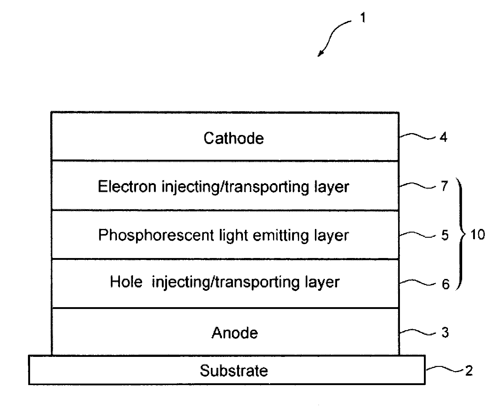
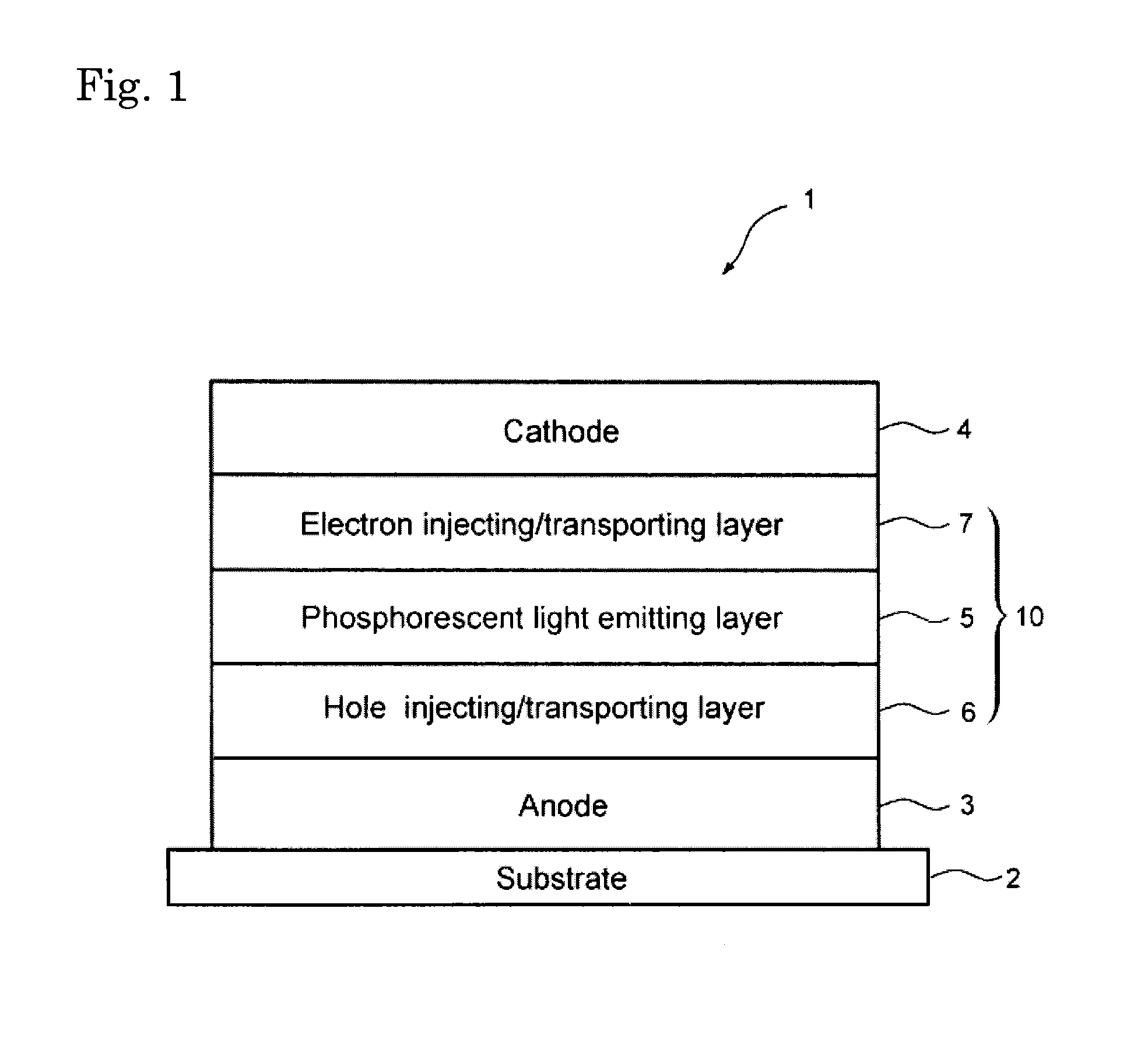
Image

Examples
synthesis example 1
Synthesis of Intermediate 1
[0283]
[0284]In argon stream, a mixture obtained by successively mixing 2-nitro-1,4-dibromobenzene (11.2 g, 40 mmol), phenylboronic acid (4.9 g, 40 mmol), tetrakis(triphenylphosphine)palladium (1.39 g, 1.2 mmol), toluene (120 mL), and a 2M aqueous solution of sodium carbonate (60 mL) was refluxed under heating for 8 h.
[0285]After cooling the reaction liquid to room temperature, the organic layer was separated and the organic solvent was removed from the organic layer by distillation under reduced pressure. The obtained residue was purified by a silica gel column chromatography to obtain intermediate 1 (6.6 g, yield: 59%). The identification of intermediate 1 was made by FD-MS (field desorption mass spectrometry) analysis.
synthesis example 2
Synthesis of intermediate 2
[0286]
[0287]In argon stream, a mixture obtained by successively mixing intermediate 1 (6.6 g, 23.7 mmol), triphenylphosphine (15.6 g, 59.3 mmol), and o-dichlorobenzene (24 mL) was heated at 180° C. for 8 h.
[0288]After cooling the reaction liquid to room temperature, the reaction product was purified by a silica gel column chromatography to obtain intermediate 2 (4 g, yield: 68%). The identification of intermediate 2 was made by FD-MS analysis.
synthesis example 3
Synthesis of Intermediate 3
[0289]
[0290]The procedure of Synthesis of intermediate 1 was repeated except for using intermediate 2 in place of 2-nitro-1,4-dibromobenzene and using 9-phenyl-9H-carbazole-3-ylboronic acid in place of phenylboronic acid. The obtained compound was identified as intermediate 3 by FD-MS analysis.
PUM
 Abstract
Description
Claims
Application Information