
Rotor structure of drive motor

a technology of drive motor and rotor, which is applied in the direction of dynamo-electric machines, magnetic circuit rotating parts, magnetic circuit shapes/forms/construction, etc., can solve the problems of reducing the output and affecting the efficiency of synchronous motor, and high price, so as to reduce the defective proportion of windings and facilitate manufacturing and assembly. , the effect of improving the no-load counter electromotive voltag

Inactive Publication Date: 2014-11-20
HYUNDAI MOTOR CO LTD
View PDF1 Cites 12 Cited by
  • Summary
  • Abstract
  • Description
  • Claims
  • Application Information

AI Technical Summary

Benefits of technology

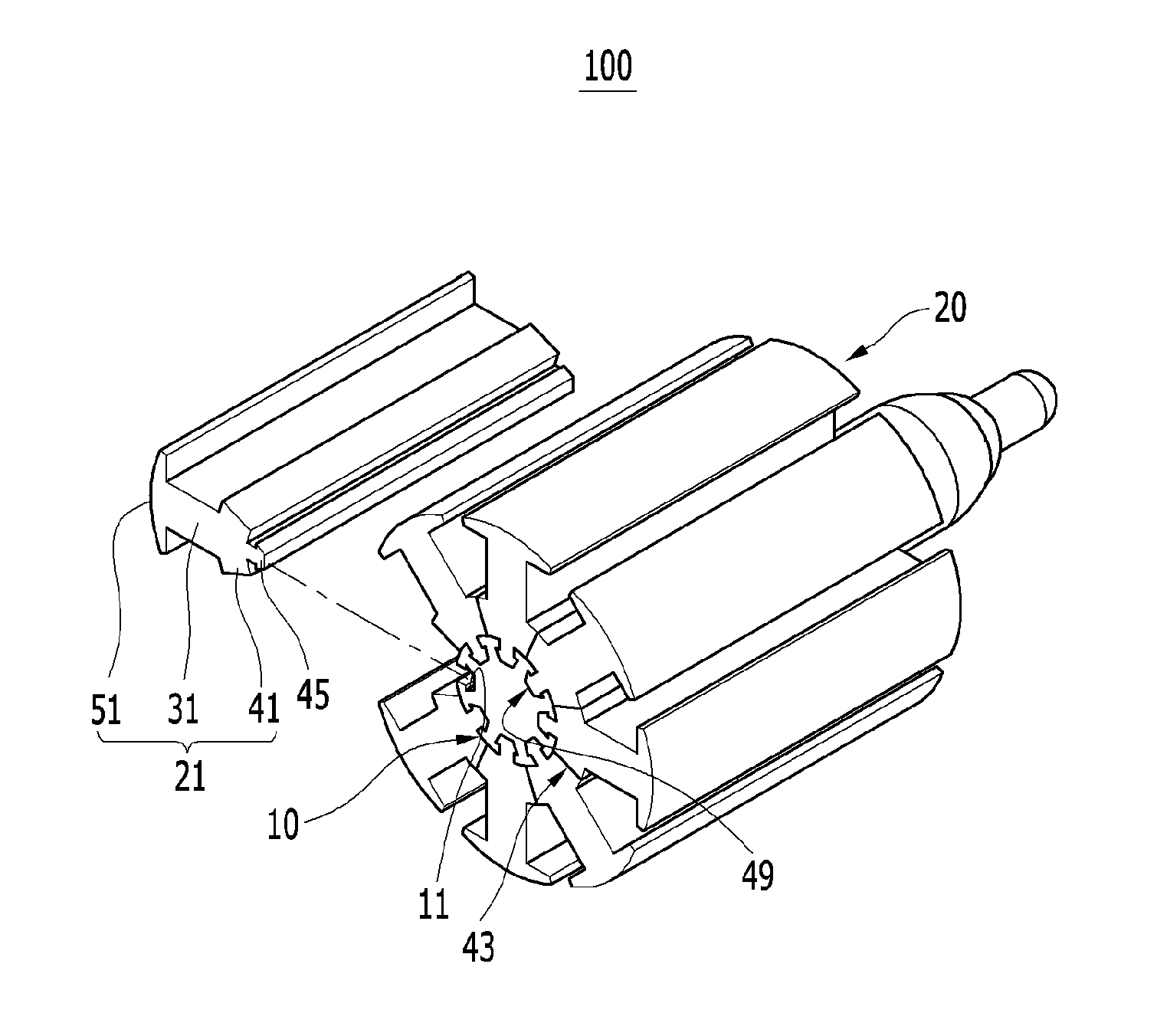
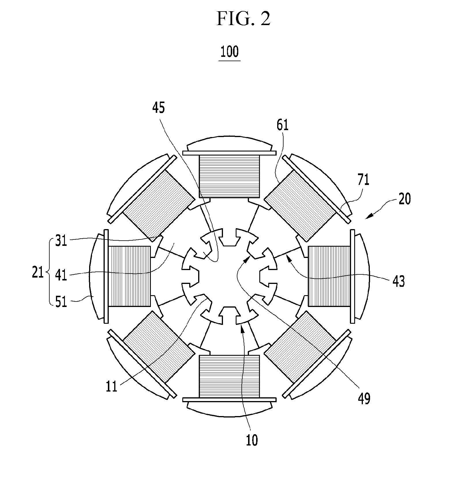
The present invention provides a rotor structure for a driving motor that increases the space factor of the coil without affecting the magnetic flux flow. The rotor core is formed of multiple blocks that are fixed around the rotary shaft, making it easier to manufacture and assemble. By winding wires around the individual blocks and positioning them out of the main magnetic flux path, the motor's efficiency is improved. The joints between the core blocks and shaft are positioned away from the main magnetic flux path, further increasing the motor's efficiency.

Problems solved by technology

However, rare earth metal elements (e.g., Nd and Dy) in the permanent magnet locally lie under the ground in some countries such as China, and the price is very high and frequently fluctuated.
Therefore, an induction motor has been recently developed, limitations of an increase in volume, weight, and size has been observed to achieve similar motor performance.
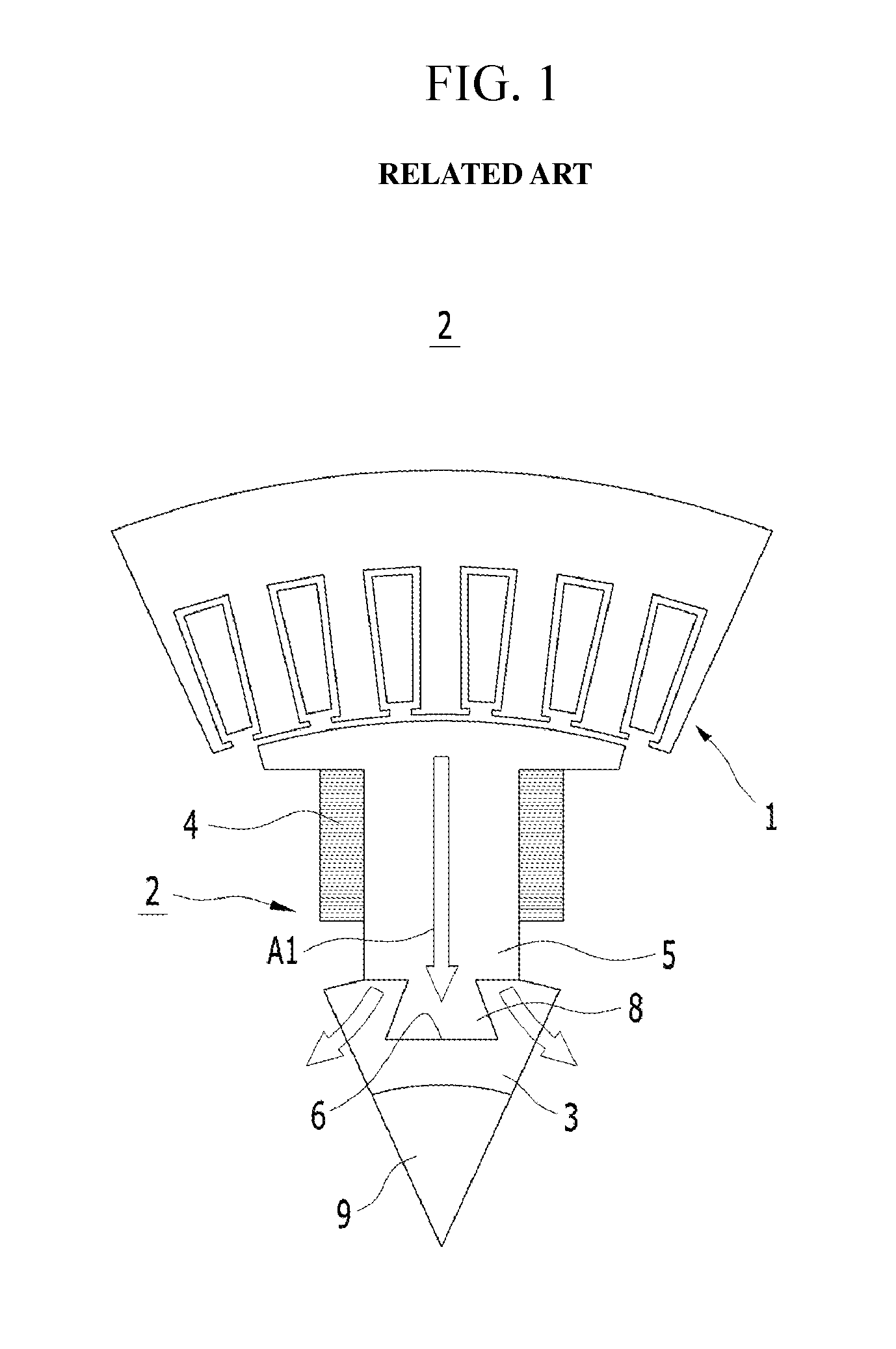
However, in the rotor 2 of the division core type of WRSM, a plurality of core blocks 5 are fitted into the rotor body 3, and thus the connection portions (e.g., division core joints) of the rotor body 3 and the core blocks 5 are positioned on a magnetic flux path A1, to influence the flow of the magnetic flux and may reduce the output and efficiency of the synchronous motor.
Further, fitting protrusions fitted within the protrusion grooves may protrude from the fitting portions.

Method used


Image

  • Rotor structure of drive motor
  • Rotor structure of drive motor
  • Rotor structure of drive motor

Examples


Embodiment Construction

[0024]It is understood that the term “vehicle” or “vehicular” or other similar term as used herein is inclusive of motor vehicles in general such as passenger automobiles including sports utility vehicles (SUV), buses, trucks, various commercial vehicles, watercraft including a variety of boats and ships, aircraft, and the like, and includes hybrid vehicles, electric vehicles, plug-in hybrid electric vehicles, hydrogen-powered vehicles, fuel cell vehicles, and other alternative fuel vehicles (e.g. fuels derived from resources other than petroleum). As referred to herein, a hybrid vehicle is a vehicle that has two or more sources of power, for example both gasoline-powered and electric-powered vehicles.

[0025]The terminology used herein is for the purpose of describing particular embodiments only and is not intended to be limiting of the invention. As used herein, the singular forms “a”, “an” and “the” are intended to include the plural forms as well, unless the context clearly indica...


PUM


Abstract

A rotor structure of a drive motor is provided. In the rotor structure of a driving motor, a rotor core is divisionally formed in a plurality of core blocks and the core blocks may be combined around an outer side of a rotary shaft.

Description

CROSS-REFERENCE TO RELATED APPLICATION[0001]This application claims priority to and the benefit of Korean Patent Application No. 10-2013-0056681 filed in the Korean Intellectual Property Office on May 20, 2013, the entire contents of which are incorporated herein by reference.BACKGROUND[0002](a) Field of the Invention[0003]An exemplary embodiment of the present invention relates to a rotor of a drive motor for environmentally-friendly vehicles. More particularly, the present invention relates to a rotor combination structure of a WRSM (Wound Rotor Synchronous Motor) using a division core type.[0004](b) Description of the Related Art[0005]In general, hybrid vehicles or electric vehicles, which are usually called environmentally-friendly vehicles, are driven by an electric motor (hereafter, also referred to as a “driving motor”) that acquire torque from electric energy. Hybrid vehicles travel in an EV (electric vehicle) mode, which is an electric vehicle mode that uses only the power ...

Claims


Application Information

Patent Timeline
Patent Type & Authority Applications(United States)
IPC IPC(8): H02K1/28
CPCH02K1/28H02K1/24
Inventor JUNG, MYEONG KYUSEO, YOUNG JINHAN, DONGYEON
Owner HYUNDAI MOTOR CO LTD
Learn More