Oscillation device, scanning-type scanner device, information terminal, phase-shift amount adjustment device, and phase-shift amount adjustment method

a technology of oscillation device and scanning type scanner, which is applied in the direction of pulse technique, instruments, television systems, etc., can solve the problems of increasing drive power, reducing and reducing the drive efficiency of oscillation device, so as to achieve significant reduction or minimize the amplitude of drive signal and the effect of significant increase in the drive efficiency

Active Publication Date: 2014-11-20
FUNAI ELECTRIC CO LTD
View PDF1 Cites 8 Cited by
  • Summary
  • Abstract
  • Description
  • Claims
  • Application Information

AI Technical Summary

Benefits of technology

[0010]In addition, preferred embodiments of the present invention provide a phase-shift amount adjustment device and a phase-shift amount adjustment method with which the drive efficiency of an oscillation device is increased by optimally adjusting an amount of phase shift in a phase shift unit of the oscillation device.
[0012]With such a configuration, deviation from integer multiples of 0° or 360° of the phase-shift amount in a complete single loop configured of an oscillator, an oscillation detection unit, and a drive unit are significantly reduced or prevented by adjusting the amount of phase shift, which enables the amplitude of the drive signal to be significantly reduced or minimized, such that drive efficiency is significantly increased.
[0014]With this configuration, changes in the amplitude of the drive signal follow fluctuations in the amount of phase shift based on the periodic signal, so the amount of phase shift is adjusted accurately.
[0016]This configuration makes it possible for the amount of phase shift to approach close to the optimal value with the second value, so the amount of phase shift is adjusted in a short period of time.
[0019]In the other configuration described above, the product detection unit preferably generates the detection signal by sampling the drive signal at the positive maximums and negative maximums of the periodic signal and integrating the values sampled at the positive maximum and the polarity inversion of the values sampled at the negative maximum. This method makes digital processing possible with a small number of samples.
[0024]With various preferred embodiments of the present invention, deviations from integer multiples of 0° or 360° of the phase-shift amount in a complete single loop including an oscillator, an oscillation detection unit, and a drive unit are significantly reduced or prevented by adjusting the amount of phase shift, which enables the amplitude of the drive signal to be significantly reduced or minimized, so the drive efficiency of the oscillation device is significantly increased.

Problems solved by technology

However, variations between individual oscillators, changes in the ambient environment of the oscillation device (such as temperature changes), and the like, cause transfer characteristics to be different from design or desired values, and as a result, the amount of phase shift in a single complete loop ends up deviating from 0°.
Thus, there are problems in that drive power is increased while drive efficiency is worsened.
Moreover, if the amount of phase shift in a single complete loop deviates too much from 0°, the additional problem of being unable to initiate self-oscillation also arises.

Method used


Image

  • Oscillation device, scanning-type scanner device, information terminal, phase-shift amount adjustment device, and phase-shift amount adjustment method
  • Oscillation device, scanning-type scanner device, information terminal, phase-shift amount adjustment device, and phase-shift amount adjustment method
  • Oscillation device, scanning-type scanner device, information terminal, phase-shift amount adjustment device, and phase-shift amount adjustment method

Examples


first preferred embodiment

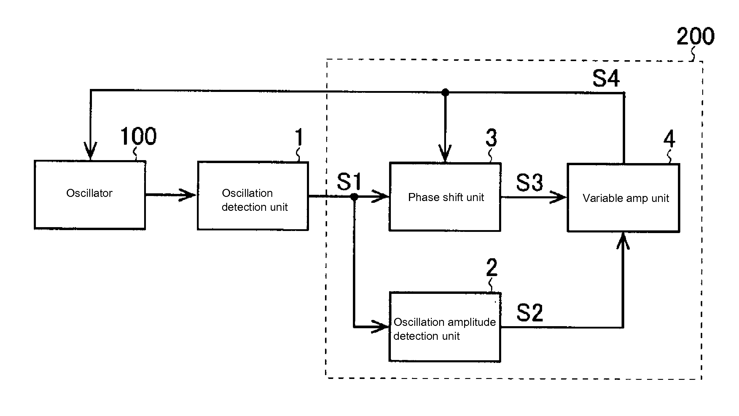
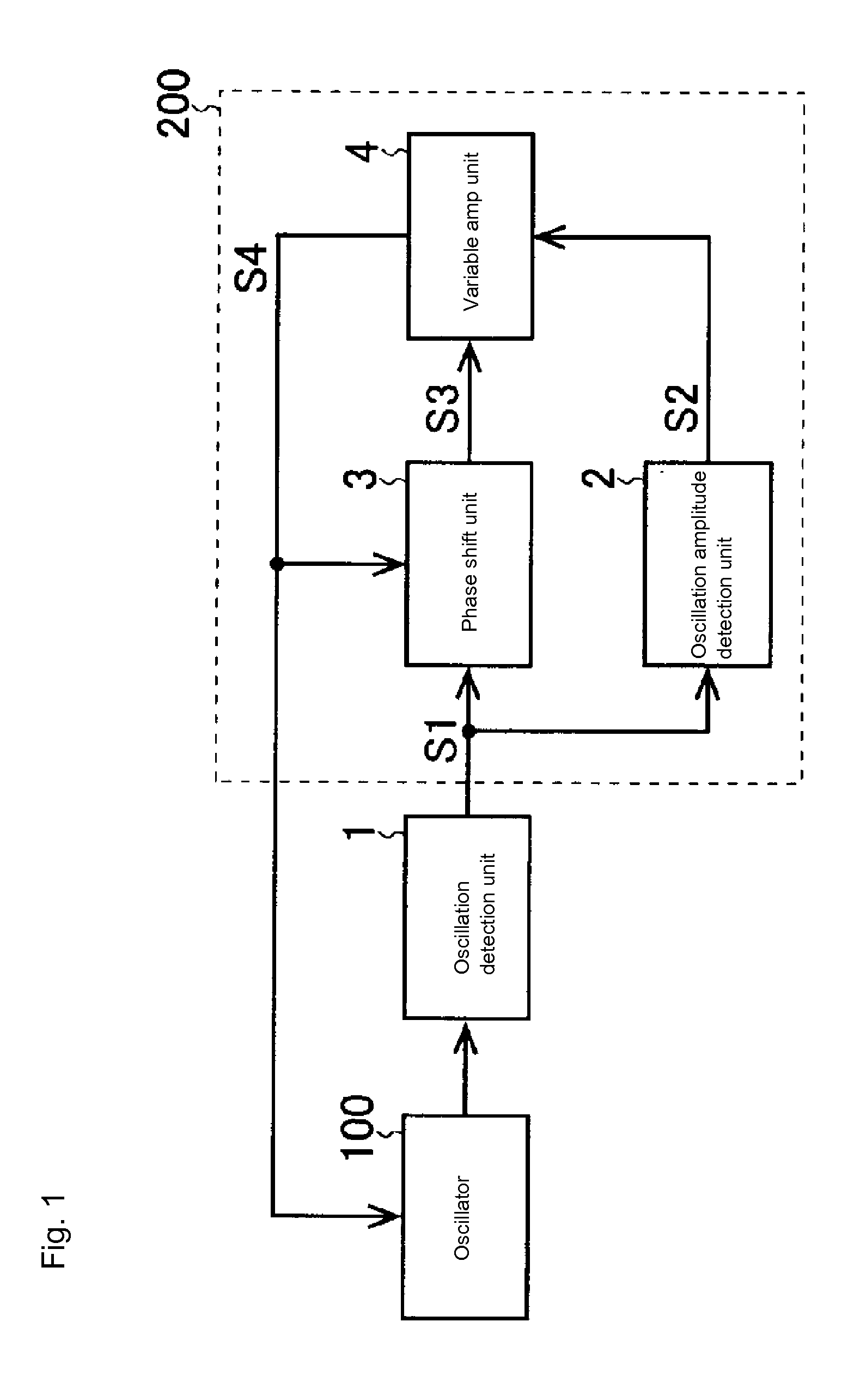
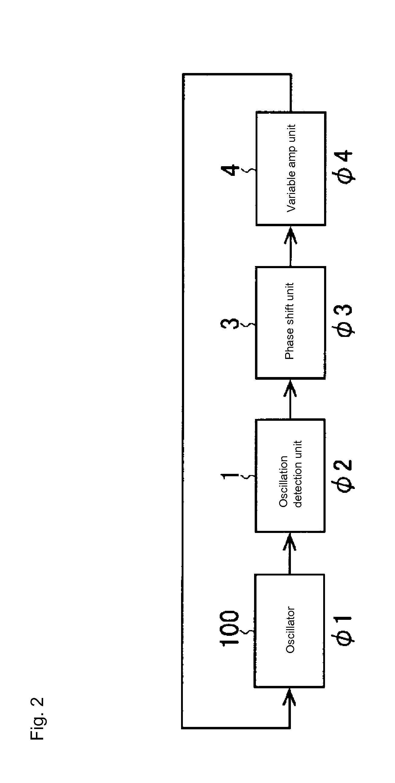
[0039]FIG. 1 is a block diagram showing the basic configuration of the oscillation device according to a first preferred embodiment of the present invention. The oscillation device according to the present preferred embodiment preferably includes an oscillator 100, an oscillation detection unit 1 which detects oscillation of the oscillator 100 and outputs an oscillation detection signal S1, and a drive unit 200 which generates a drive signal S4 in keeping with the oscillation detection signal S1 and outputs the drive signal 4 to the oscillator 100.

[0040]One non-limiting example of the configuration of the oscillator 100 is one that includes a piezoelectric element to which a drive signal S4 (constituting a voltage signal) is applied and a vibrator which oscillates accompanying the deformation of this piezoelectric element. Another example is a configuration that includes an electromagnet to which a drive signal S4 (constituting a current signal) is applied and a vibrator which oscil...

second preferred embodiment

[0069]The oscillation device according to the second preferred embodiment of the present invention preferably is identical to the oscillation device according to the first preferred embodiment of the present invention, except for the method for generating the detection signal S5.

[0070]In the present preferred embodiment, the product detection unit 33 uses as its detection signal S5 a signal that samples the product of the periodic signal f(t) and the drive signal S4 at every half-period of the periodic signal f(t) when the periodic signal f(t) is at a peak value (see FIG. 9). In this case, sampling occurs twice in one period of the periodic signal f(t).

[0071]In the present preferred embodiment, the detection signal S5 includes a plurality of discrete outputs, so the value of the detection signal S5 refers to the average value of the discrete output values.

[0072]The oscillation device according to the present preferred embodiment as described above exhibits basically the same effects...

third preferred embodiment

[0073]The oscillation device according to a third preferred embodiment of the present invention preferably is identical to the oscillation device according to the first preferred embodiment of the present invention, except for the fact that the configuration of the phase shift unit 3 is modified and that the oscillation device is provided with a drive signal output terminal (not shown) which outputs a drive signal S4 to the outside.

[0074]In the present preferred embodiment, the phase shift unit 3 includes a phase shifter 35 and a control signal input terminal 36 which takes, as its input, control signals that are sent from outside the oscillation device as shown in FIG. 10. The phase shifter 35 shifts the phase of the oscillation detection signal S1 by a specified phase-shift amount to generate a phase shift signal S3 and then adjusts the specified phase-shift amount according to the control signal that is input to the control signal input terminal 36.

[0075]Furthermore, the phase-sh...


PUM


Abstract

An oscillation device includes an oscillator, an oscillation detection unit that detects oscillation of the oscillator and outputs an oscillation detection signal, and a drive unit that generates a drive signal in keeping with the oscillation detection signal and outputs the drive signal to the oscillator. The drive unit includes a phase shift unit that shifts the phase to provide the drive signal as positive feedback to the oscillator. The phase shift unit includes a disturbance generating unit that outputs the periodic signal, a fluctuation unit that causes the amount of phase shift to fluctuate based on the periodic signal, a drive amplitude detection unit that detects the amplitude of the drive signal and outputs a drive amplitude signal, a product detection unit that outputs a detection signal after performing product detection on the drive amplitude signal based on the periodic signal, and an adjustment unit that adjusts the phase-shift amount based on the detection signal.

Description

BACKGROUND OF THE INVENTION[0001]1. Field of the Invention[0002]The present invention relates to an oscillation device which causes an oscillator to self-oscillate, a scanning-type scanner device such as a laser projector or laser rangefinder that is equipped with this oscillation device, and an information terminal equipped with this oscillation device. The present invention also relates to a phase-shift amount adjustment device and a phase-shift amount adjustment method which adjust an amount of phase shift in a phase shift unit of this oscillation device.[0003]2. Description of the Related Art[0004]Conventional oscillation devices cause an oscillator to self-oscillate by supplying the oscillator with a drive signal at a frequency that is made to match the mechanical resonance frequency of the oscillator (for examples, see Japanese Patent Application Laid-Open Publication No. 2008-124192, Japanese Patent Application Laid-Open Publication No. 2005-351820, and Japanese Patent Applic...

Claims


Application Information

Patent Timeline
Patent Type & Authority Applications(United States)
IPC IPC(8): H03K5/01H03B5/24H04N1/04
CPCH03B5/24H03K2005/00286H03K5/01H04N1/04H03K5/13G02B26/0833G02B26/105H03B5/20H04N3/08H03B5/32
Inventor HORIBE, RYUSUKEINOUE, NAOKIMURAYAMA, MANABU
Owner FUNAI ELECTRIC CO LTD
Why Eureka
Try Eureka