System and a method for optimization and management of demand response and distributed energy resources

Inactive Publication Date: 2014-11-20
AUTOGRID SYST INC
View PDF4 Cites 13 Cited by
  • Summary
  • Abstract
  • Description
  • Claims
  • Application Information

AI Technical Summary

Benefits of technology

The present invention provides a system for optimizing and managing demand response resources in real-time. The system includes a resource modeler, a forecasting engine, an optimizer, a dispatch engine, and a baseline engine. The resource modeler keeps track of available demand response resources and their characteristics. The forecasting engine performs short-term forecasts of aggregate load and available load-sheds for individual loads connected to the system. The optimizer determines the optimal dispatch of demand response under a given cost function. The dispatch engine implements the optimal dispatch. The baseline engine detects demand reduction in response to a demand response event or price notification for significantly reducing the cost of participation in demand response. The patent also includes a technique for identifying small signals in the background of very large baseline signals. Overall, this system enables more efficient and effective management of demand response resources for achieving cost-effectiveness and reduced environmental impact.

Problems solved by technology

Traditionally, price-based DR has been used to shift peak load but has not adequately addressed other electrical properties such as congestion or power quality.
Existing demand response programs offer comparatively coarse control providing jagged responses that are often difficult to distinguish from normal whole site electric meter profiles using traditional baseline techniques.
When closed-loop controls are used to target a specific shed value, ramp-rates are still substantially uncontrolled.
Traditional telemetry equipment costs upwards of $20,000 per monitored load.
Today, all of these programs sit in their separate silos and there is no way to coordinate the execution of these programs over geographies and customers.
This leads to a significant reduction in overall efficiency of the system.

Method used


Image

  • System and a method for optimization and management of demand response and distributed energy resources
  • System and a method for optimization and management of demand response and distributed energy resources
  • System and a method for optimization and management of demand response and distributed energy resources

Examples


Embodiment Construction

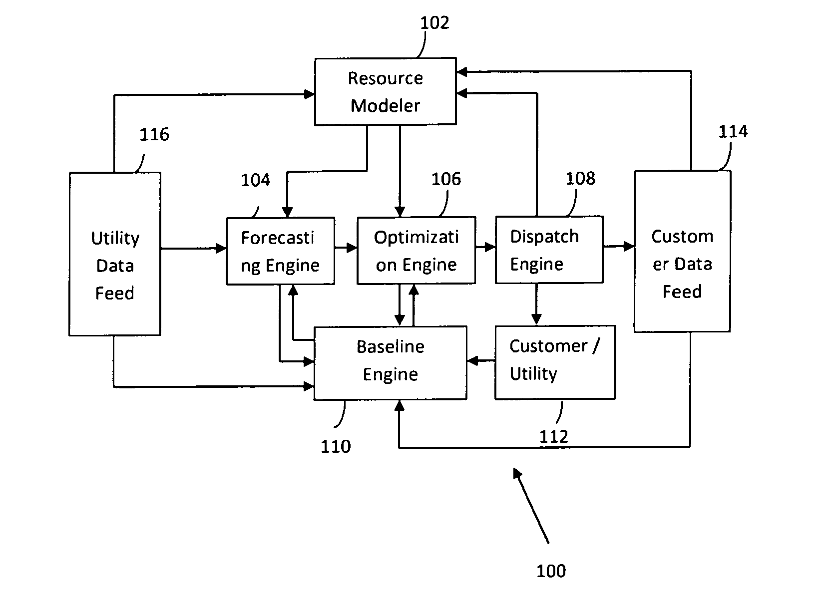
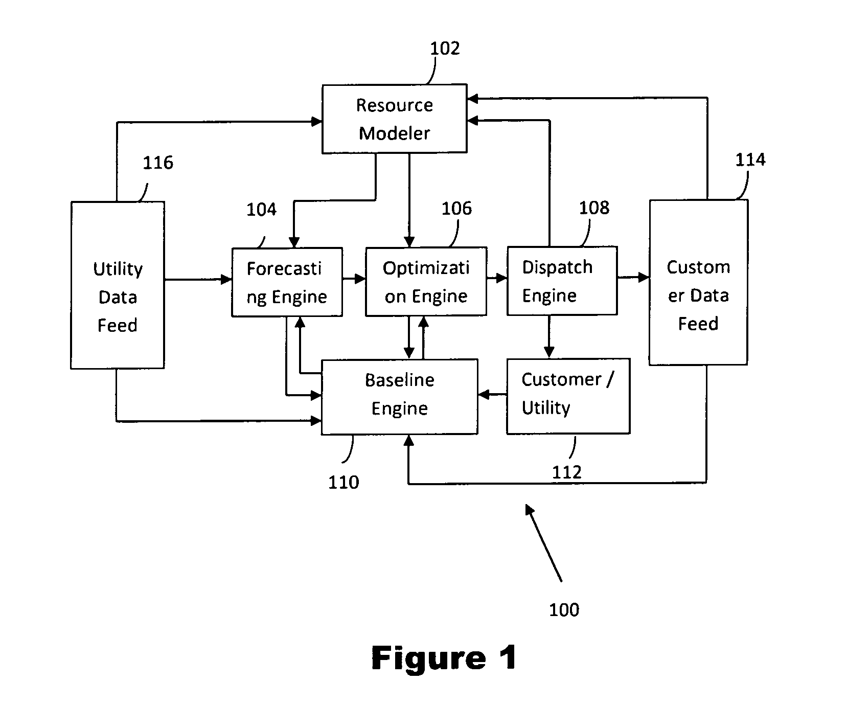
[0014]DROMS-RT is a highly distributed Demand Response Optimization and Management System for Real-Time power flow control to support large scale integration of distributed generation into the grid.

[0015]Demand response programs help in reducing the energy costs and system integrity for a few critical hours during the year. The demand response programs also encourage end customers to reduce load at their facilities, and to participate in the price response program or enter into the forward capacity market through a demand response provider. Demand Response services are substantially less expensive and cleaner than other forms of ancillary services options currently available.

[0016]In an embodiment of the present invention, a scalable, web-based software as a service platform is provided that provides all program design, resource modeling, forecasting, optimal dispatch, and measurement functionality. The invention provides a method to optimize demand response and distributed energy r...


PUM


Abstract

A system and a method for optimization and management of Demand Response in real time manner is provided. The system employs a resource modeler, a forecasting engine, an optimizer, a dispatch engine, and a baseline engine. The system is built using open framework standards based signaling and data collection, and is offered under a “Software-as-a-Service” model to significantly reduce the cost of participation in demand response. It uses off the shelf information and communication technology (ICT) and controls equipment.

Description

CROSS-REFERENCE TO RELATED APPLICATION(S)[0001]This application claims the benefit of priority to U.S. Provisional Patent Application No. 61 / 535,369, filed Sep. 16, 2011, entitled “Software-as-a-Service (SaaS) for Optimization and Management of Demand Response and Distributed Energy Resources”, and claims the benefit of priority to U.S. Provisional Patent Application No. 61 / 535,371, filed Sep. 16, 2011, entitled “Multi-Channel Communication of Demand Response Information between Server and Client”, and claims the benefit of priority to U.S. Provisional Patent Application No. 61 / 535,365, filed Sep. 16, 2011, entitled “System and Method for Optimization of Demand Response and Distributed Energy Resources and Management Thereof”, the contents of each of which are hereby incorporated by reference in their entireties.FIELD OF THE INVENTION[0002]The present invention relates generally to a demand response (DR) and management of distributed energy resources (DER) system and more particular...

Claims


Application Information

Patent Timeline
IPC IPC(8): G06Q50/06G06Q10/06
CPCG06Q10/0631G06Q50/06G06Q10/04Y02B70/3225Y04S20/222H02J2310/64H02J3/003H02J3/14Y04S50/10G01R21/00H04L67/141
Inventor NARAYAN, AMITSCHWARZ, HENRYSINGH, RAJEEV KUMARBHAT, VIJAY SRIKRISHNABAHL, ABISHEK
Owner AUTOGRID SYST INC
Why Eureka
Try Eureka