
Synthetic rope for powered blocks and methods for production

a technology of powered blocks and synthetic ropes, applied in the field of synthetic ropes, can solve the problems of reducing the strength of steel wire ropes for a given diameter, increasing the longevity of certain steel wire ropes, and failing to increase either the strength of ropes or their longevity, so as to improve strength retention, improve longevity, and improve the effect of strength

Inactive Publication Date: 2014-11-27
HAMPIDJAN
View PDF11 Cites 5 Cited by
  • Summary
  • Abstract
  • Description
  • Claims
  • Application Information

AI Technical Summary

Benefits of technology

The present invention provides a strong synthetic strength member that uses rope and is designed for use with powered blocks. The strength of the rope is improved, meaning less of it is needed for a given application, resulting in a lower cost per unit.

Problems solved by technology

While attempts and methods of adhering a steel wire rope's strength member to a sheath surrounding a steel strength member have failed in increasing the steel wire ropes strength, and actually reduce the steel wire rope's strength for a given diameter (a rope's strength necessarily measured in relation to its diameter) such attempts and methods have succeeding in increasing the longevity of certain steel wire ropes.
However, in the case of ropes formed with synthetic and / or mainly synthetic strength members, all known attempts to increase the strength and / or the longevity of synthetic ropes by adhering a sheath surrounding a strength member to the synthetic and / or mainly synthetic strength member have failed to increase either the strength of the rope or its longevity, and in fact do the opposite.
That is, known methods of adhering a synthetic rope's strength member to a sheath surrounding such strength member actually decrease both the strength and longevity of the ropes.
For this reason, such known constructions increase not only the expense of the rope, but also its diameter and thus associated drags in for example water, as well as its weight and thus associated costs for structures affixing, floating, sustaining or otherwise supporting such ropes.
As a consequence, it is contrary to the trend in the industry and against the state of the art to adhere to a synthetic rope's strength member a sheath surrounding such strength member.
As another consequence, it is accurate to state that it is contrary to the trend in the industry and against the state of the art to actually improve a rope's strength by adhering a sheath to the ropes strength member, especially by adhering a sheath to a synthetic and / or mainly synthetic ropes synthetic and / or mainly synthetic strength member, and that such result would be surprising to those skilled in the art.
It is well known that synthetic high strength ropes have a drawback of being very expensive.
Furthermore, synthetic high strength ropes are prone to a much more rapid rate of degradation than natural, e.g. wire ropes, and are quicker to experience abrasion induced failure when used on powered blocks, whether in protected environments or in high temperature and abrasive environments, as opposed to when such synthetic high strength ropes are used in static applications.
This is because, as mentioned above, known constructions and methods for adhering a synthetic strength member to a sheath surrounding such strength member actually decrease the strength of as well as decrease the longevity of known synthetic ropes, including synthetic ropes for use with powered blocks.
Ropes having sheaths such as plastic sheaths surrounding a strength member, and ropes having synthetic barriers including adhesives and thermoplastics between a strength member and a sheath have failed to be successfully used with powered blocks, whether such ropes are synthetic or natural ropes, and the present state of the art and the current trend in the industry is that natural as well as synthetic strength members used with powered blocks have no such type of sheath, as the cost of forming such sheaths has not been proved to be of benefit.
However, the very high costs of such high strength synthetic strength member containing ropes compared to natural high strength ropes, e.g. wire ropes, and the fact that such high strength synthetic strength member containing ropes when used with powered blocks experience rather fast deterioration of their sheaths and ultimately of the synthetic strength members, has resulted in the fact that today only limited market acceptance has been gained for high strength synthetic strength member containing ropes for use with powered blocks.
That is, known high strength synthetic strength member containing ropes used with powered blocks are known for rather quickly experiencing abrasion induced failure, and for experiencing a rather rapid strength degradation prior to absolute failure for their cost.
Due to the extremely high cost of such ropes, their premature failure and short life spans when used with powered blocks, the adoption of high strength synthetic strength member ropes for use with powered blocks has been limited.
For example, the vast majority of the world's trawlers even in highly developed regions continue to use wire rope as trawl warps, despite the great weight and safety concerns caused by such weight when the natural high strength rope is stored on a trawl winch—i.e. vessel instability, it being well known that the weight of such stored wire trawling warps has often been implicated in vessel capsize.
However, this embodiment has failed to be commercially accepted for the reasons taught above, i.e. due to the fact that the strength of the cable is reduced by such construction.

Method used


Image

  • Synthetic rope for powered blocks and methods for production
  • Synthetic rope for powered blocks and methods for production

Examples


Embodiment Construction

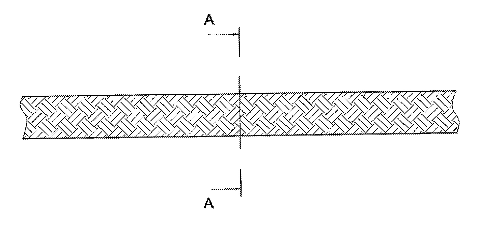
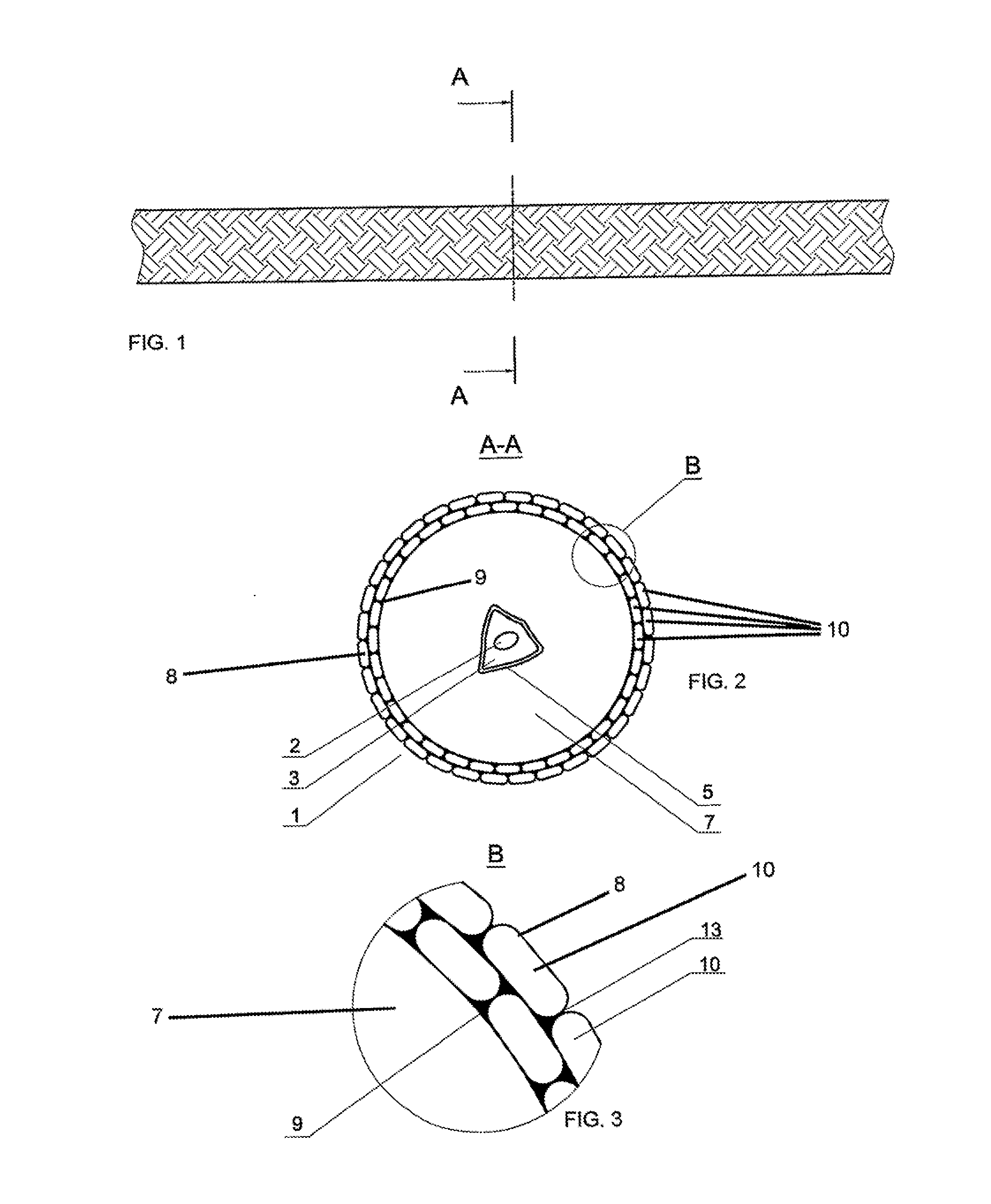
[0041]FIG. 2 and FIG. 3 illustrate essential constructional components of one of the most preferred embodiments for use with high tension powered blocks of the rope for powered blocks and winches of the present disclosure that is identified by the general reference character 1. FIG. 2 depicts a preferably thermoplastic shaped supportive core 3 enclosing a lead core 2, the shaped supportive core 3 being enveloped within a flow shield sheath 5. Strength member 7 encloses the combination of the shaped supportive core 3, its enveloping flow shield sheath 5 and its lead core 2. Sheath 8 preferably is of a braided construction and is adhered to strength member 7 by elastic adhesive substance layer 9, that preferably is formed of a settable adhesive substance. Preferably braided sheath 8 is formed of multiple coverbraid strands 10 by use of a braiding machine, the coverbraid strands 10 preferably are of a laid construction. Optionally, and preferably, as shown in more easily visible detail...


PUM

PropertyMeasurementUnit
temperatureaaaaaaaaaa

Abstract

Disclosed is a method for producing a high strength synthetic strength member (7) containing rope (1) capable of being used with powered blocks where such rope has lighter weight and similar or greater strength than steel wire strength member containing ropes used with powered blocks. Disclosed also is the product resulting from such method. The product includes a synthetic strength member, a first synthetic portion (9) and a second synthetic portion. The first synthetic pillion is enclosed within the strength member and the second synthetic portion is situated external the strength member. At least a portion of the second synthetic portion also is situated internal a sheath (8) formed about the strength member. The second synthetic portion has a minimal of 8% at a temperature of between negative 20 and negative 15° C.

Description

TECHNICAL FIELD [0001]The present disclosure relates generally to the technical field of synthetic ropes and, more particularly, to a rope that preferably is made from synthetic polymeric material, that has a rather high breaking strength and that also has a rather light weight compared to steel wire rope and that is capable of being used with powered blocks, traction winches, powered winches, powered drums, drum winches, powered capstans and in general any powered turning element and / or rotating element capable of applying force to a rope (hereinafter aggregately known as “powered blocks”). Such synthetic ropes include but are not limited to tow ropes, towing warps, trawl warps (also known as “trawlwarps”), deep sea lowering and lifting ropes, powered block rigged mooring ropes, powered block rigged oil derrick anchoring ropes used with blocks and also with powered blocks, superwides and paravane lines used in seismic surveillance including but not limited to used with towed arrays...

Claims


Application Information

Patent Timeline
Patent Type & Authority Applications(United States)
IPC IPC(8): D07B7/02
CPCD07B7/027D07B2201/2041D07B2201/1096D07B2207/4063D04C1/12D07B1/025D07B1/185D07B5/12D07B7/165D07B2201/102D07B2201/2048D07B2201/2053D07B2201/2066D07B2201/2067D07B2201/2074D07B2201/209D07B2201/2095D07B2201/2096D07B2205/2003D07B2205/2014D07B2205/2042D07B2205/2064D07B2205/2096D07B2207/405D07B2207/4059D07B2207/4068D07B2301/258D07B2301/3591D07B2401/205D07B2401/2055D07B2501/2038D07B2501/2061D07B2801/10D07B2801/60D07B2801/24D07B2801/14D07B2801/16
Inventor ERLENDSSON, HJORTUR
Owner HAMPIDJAN
Learn More