Lithography device with eddy-current brake

a technology of eddy-current brake and lithography device, which is applied in the direction of photomechanical apparatus, asynchronous induction clutch/brake, instruments, etc., can solve the problems of increasing the damping effect, and achieve the effect of simplifying the design of the actuator and low maintenan

Active Publication Date: 2014-11-27
CARL ZEISS SMT GMBH
View PDF2 Cites 36 Cited by
  • Summary
  • Abstract
  • Description
  • Claims
  • Application Information

AI Technical Summary

Benefits of technology

[0069]Similar advantageous effects, as in the arrangement as per the first embodiment, also emerge from this arrangement. Thus, the circular arrangement of the stacks of magnets 66-1 . . . 66-12 enables damping in a number of degrees of freedom. To be more precise, broad-band damping in all six degrees of freedom is also achieved in this arrangement. Furthermore, the damping is frictionless, and so it is low maintenance and ensures a long service life of the damping arrangement. A further advantage of this arrangement is that it is very compact. Furthermore, the rigidity is not influenced by the proposed arrangement, and no additional eigenmodes are generated, as is the case when damping using rubber elements.
[0070]Furthermore, the magnet arrangement 66 is in this embodiment fixedly connected to the reaction mass 68 via the coil 62. The magnet arrangement 66 therefore contributes to the reaction mass or can be considered to be part of the reaction mass. As a result, it is possible to use more rigid spring elements 65, simplifying the design of the actuators.
[0071]In the magnet arrangement of the second embodiment, the magnets are arranged in stacks 66-1 to 66-12. The magnets of different stacks 66-1 to 66-12 that are arranged in the same x-y plane respectively constitute a set of magnets arranged in an arc-shaped arrangement whose arc extends over 360° in the x-y plane. In the arrangement shown in FIG. 7, there are three of such sets of magnets, stacked upon each other in the z-direction. Each of those sets of magnets is roughly disk-shaped. Now, since these sets of magnets are stacked upon each other in the z-direction, the primary direction to be damped is also the z-direction. However, it is not necessary to stack these magnets linearly, and they can also be stacked upon each other in arc-shapes. This is explained in the following with reference to FIGS. 9 and 10.
[0072]FIG. 9 shows a magnet arrangement 80 of an eddy current damper in accordance with a first variant of the third embodiment. It should be noted that for illustrative reasons, FIG. 9 shows only the magnets of the eddy current damper and other elements have been omitted. As in the arrangement of FIG. 7, the magnet arrangement 80 in FIG. 9 is also composed of roughly disk-shaped sets of magnets that are stacked one upon the other. Also, like in FIG. 7, also in the arrangement of FIG. 9, each set of magnets includes 12 trapezoid magnets 82-1 to 82-12 (only the magnets 82-1 and 82-7 are shown in FIG. 9). Whereas there are three of such sets of magnets in the embodiment shown in FIG. 7 (i.e. each stack includes three magnets), there are four of such sets of magnets in the embodiment shown in FIG. 9 (i.e. each stack includes four magnets, denoted as e.g. 82-1a to 82-1d).

Problems solved by technology

Hence, as a result of such an alternating arrangement of the magnets, the magnetic field along the primary direction to be damped frequently changes the direction thereof and therefore increases the damping effect.

Method used


Image

  • Lithography device with eddy-current brake
  • Lithography device with eddy-current brake
  • Lithography device with eddy-current brake

Examples


first embodiment

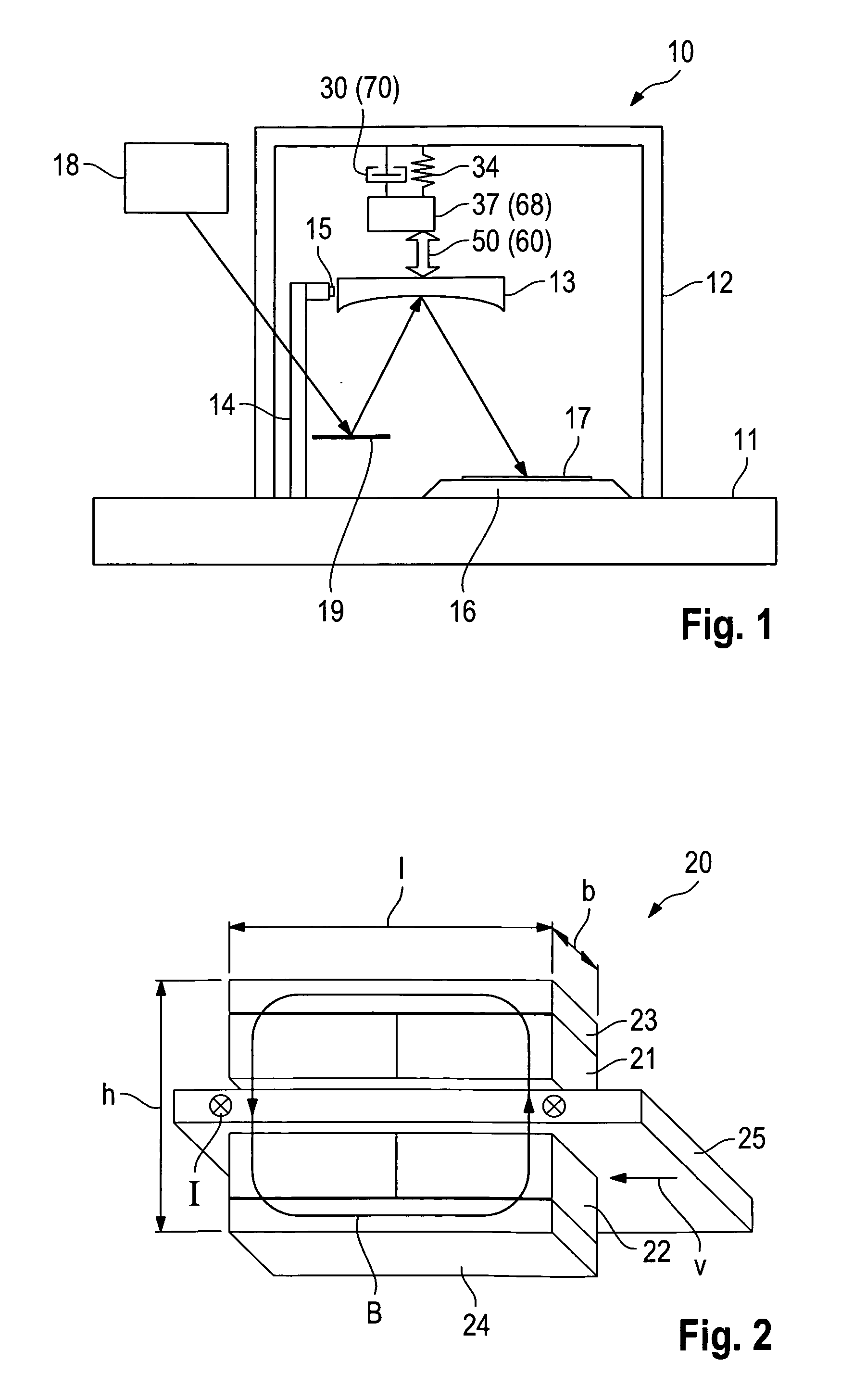
[0036]FIG. 1 shows a schematic view of a lithography device 10 as per a first embodiment. This lithography device 10 comprises a base plate 11, on which a holder frame 12 for holding at least one optical element 13, and also a measurement frame 14 for holding a sensor arrangement 15 are provided. The lithography device 10 typically has a plurality of optical elements. However, merely one optical element 13 is illustrated in an exemplary fashion in FIG. 1 in order to explain the functionality of the lithography device 10 schematically.

[0037]A wafer receptacle 16 is provided below the optical element 13 in the illustrated example; a wafer 17, e.g. a silicon wafer, can be held in the wafer receptacle. By way of example, the wafer receptacle 16 can be embodied as a step-and-scan system, which moves the wafer 17 step-by-step relative to the base plate 11, both during the exposure and during the exposure breaks.

[0038]An illumination device 18 is provided above the optical element 13; it g...

second embodiment

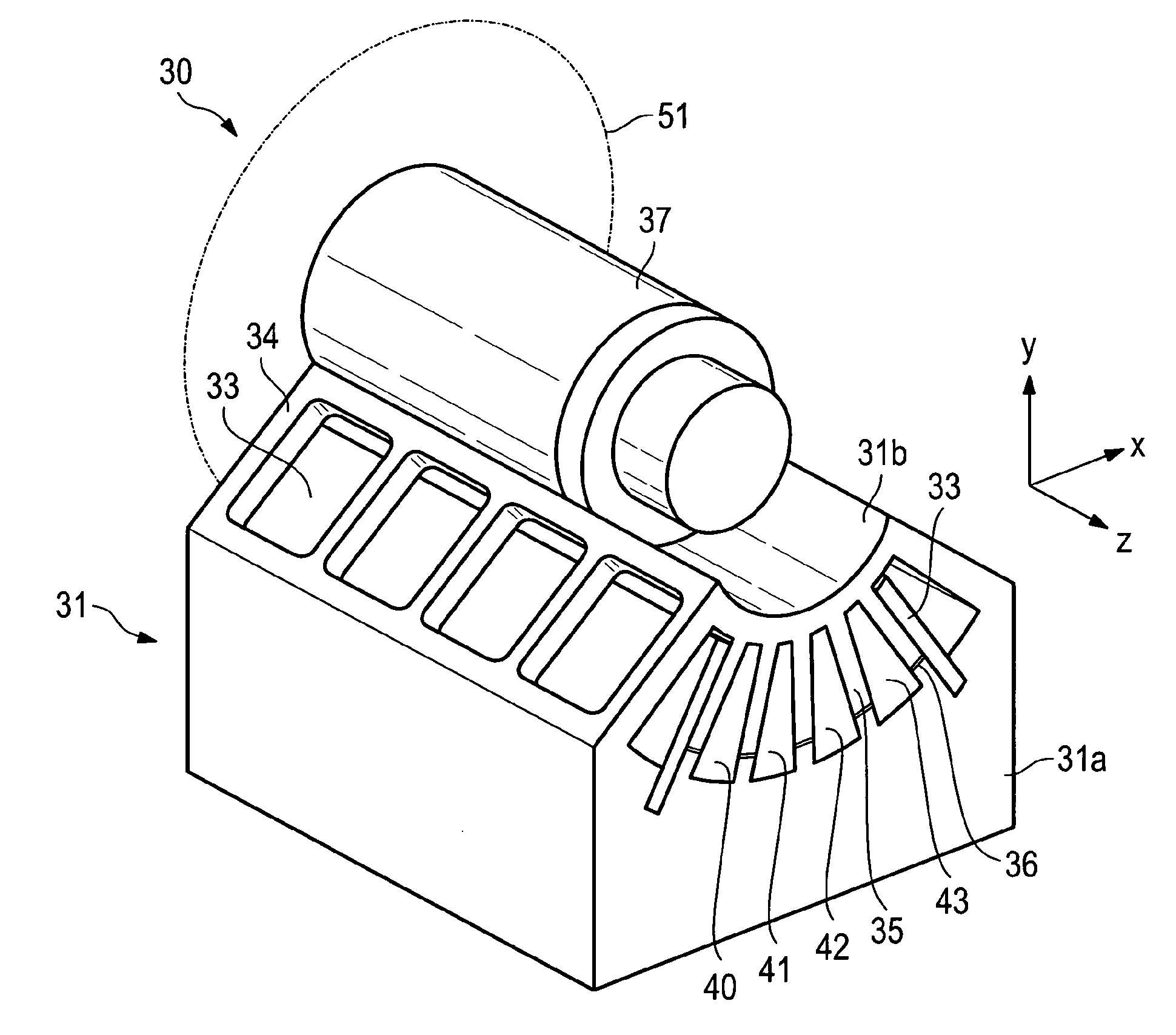
[0060]In the lithography device 10 as per the first embodiment, the magnets 40-43 are rigidly connected to the holder frame 12 via the holder device 31, while the fins 35 can move between the magnets with respect to the holder frame 12 and are rigidly connected to the reaction mass 37. However, a reverse arrangement is also possible, in which the magnets are rigidly connected to the reaction mass. Such an arrangement will be described in the following second embodiment.

[0061]A lithography device 10 as per the second embodiment has the same schematic design as illustrated in FIG. 1, and so a more detailed explanation of same is abstained from in the following text. FIG. 6 schematically shows the design of an actuator 60 with an integrated damping device 70, which is embodied as an eddy-current brake. FIG. 7 shows the arrangement of the magnets of this damping device 70. FIG. 8 shows a flat projection of the magnet arrangement. The z-axis in FIG. 8 is identical to the z-axis in FIGS. ...

third embodiment

[0071]In the magnet arrangement of the second embodiment, the magnets are arranged in stacks 66-1 to 66-12. The magnets of different stacks 66-1 to 66-12 that are arranged in the same x-y plane respectively constitute a set of magnets arranged in an arc-shaped arrangement whose arc extends over 360° in the x-y plane. In the arrangement shown in FIG. 7, there are three of such sets of magnets, stacked upon each other in the z-direction. Each of those sets of magnets is roughly disk-shaped. Now, since these sets of magnets are stacked upon each other in the z-direction, the primary direction to be damped is also the z-direction. However, it is not necessary to stack these magnets linearly, and they can also be stacked upon each other in arc-shapes. This is explained in the following with reference to FIGS. 9 and 10.

[0072]FIG. 9 shows a magnet arrangement 80 of an eddy current damper in accordance with a first variant of the third embodiment. It should be noted that for illustrative re...


PUM

PropertyMeasurementUnit
angleaaaaaaaaaa
angleaaaaaaaaaa
angleaaaaaaaaaa

Abstract

A lithography device includes an eddy-current brake for damping the movement of a structural element of the lithography device. The eddy-current brake includes a plurality of magnets disposed in an arc-shaped arrangement, and a plurality of electrically conductive sheets arranged respectively between adjacent ones of the magnets. A relative movement between the magnets and the electrically conductive sheets in a direction to be damped inducing eddy currents in the electrically conductive sheets.

Description

CROSS-REFERENCE TO RELATED APPLICATIONS[0001]The present application is a continuation of, and claims benefit under 35 USC 120 to, international application PCT / EP2013 / 000480, filed Feb. 19, 2013, which claims benefit under 35 USC 119 of German Patent Application No. 10 2012 202 553.7, filed on Feb. 20, 2012. The entire contents of German Patent Application No. 10 2012 202 553.7 and international application PCT / EP2013 / 000480 are incorporated herein by reference.FIELD OF THE INVENTION[0002]The invention relates to a lithography device with an eddy-current brake for damping a structural element of the lithography device.RELATED ART[0003]Such lithography devices are used for example in the manufacture of integrated circuits or ICs in order to image a mask pattern in a mask onto a substrate such as, for example, a silicon wafer. In the process, a light beam generated by an illumination device is, for example, directed onto the substrate through the mask. An exposure lens is provided fo...

Claims


Application Information

Patent Timeline
Patent Type & Authority Applications(United States)
IPC IPC(8): H02K49/04G03F7/20H02K49/10
CPCH02K49/04G03F7/70258H02K49/10G03F7/70766G03F7/70825G03F7/709
Inventor VOGLER, ALEXANDERHAUF, MARKUS
Owner CARL ZEISS SMT GMBH
Why Eureka
Try Eureka