Supercharge Your Innovation With Domain-Expert AI Agents!

Ramp circuit and direct current (DC)- DC converter thereof

Active Publication Date: 2014-11-27
MAGNACHIP SEMICONDUCTOR LTD
View PDF4 Cites 2 Cited by
  • Summary
  • Abstract
  • Description
  • Claims
  • Application Information

AI Technical Summary

Benefits of technology

The patent text describes a DC-DC converter that uses a ramp circuit to adjust the slope of a ramp signal based on changes in input and output voltage. This improves the output characteristics of the converter.

Problems solved by technology

However, the current-controlled mode DC-DC converter reduces the number of devices outside the chip or a size of the device by comparison to a DC-DC converter in the voltage-controlled mode.
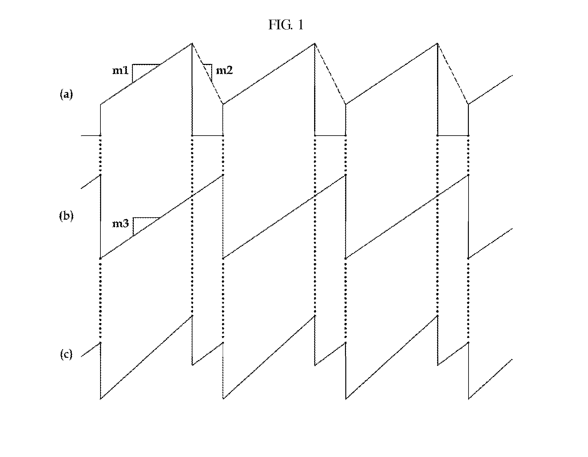
When the value of the slope m3 of the ramp signal is not suitably compensated, several issues arise.
When the slope m3 of the ramp signal is too small, the sub-harmonic oscillation is not removed properly.
When a slope of the ramp signal is set by considering a case in which an input voltage is at its lowest, excessive slope compensation is potentially performed when the input voltage is increased.
Thus, the excessive slope compensation potentially leads to slope compensation that is more than a preset driving range, to impair dynamic characteristics of the DC-DC converter.
When the input voltage is reduced with respect to the driving range that the ramp circuit is able to compensate for, the slope compensation is not accomplished, and thus the sub-harmonic oscillation is still present.
This means that the ramp circuit, which is used for eliminating the sub-harmonic oscillation, is not functioning properly.

Method used


Image

  • Ramp circuit and direct current (DC)- DC converter thereof
  • Ramp circuit and direct current (DC)- DC converter thereof
  • Ramp circuit and direct current (DC)- DC converter thereof

Examples


Embodiment Construction

[0061]The following detailed description is provided to assist the reader in gaining a comprehensive understanding of the methods, apparatuses, and / or systems described herein. However, various changes, modifications, and equivalents of the systems, apparatuses and / or methods described herein will be apparent to one of ordinary skill in the art. The progression of processing steps and / or operations described is an example; however, the sequence of and / or operations is not limited to that set forth herein and may be changed as is known in the art, with the exception of steps and / or operations necessarily occurring in a certain order. Also, descriptions of functions and constructions that are well known to one of ordinary skill in the art may be omitted for increased clarity and conciseness.

[0062]The features described herein may be embodied in different forms, and are not to be construed as being limited to the examples described herein. Rather, the examples described herein have bee...


PUM


Abstract

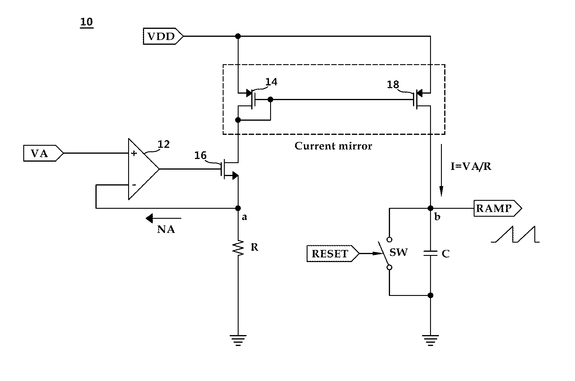
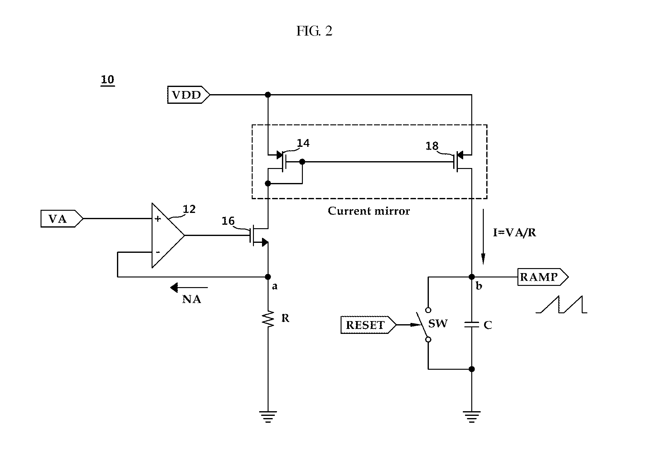
Provided are a ramp circuit and a DC-DC converter. The ramp circuit generates a current flowing in a resistor using voltages affected by an output voltage and an input voltage of a DC-DC converter, and generates a ramp signal through copying of the current and charging and discharging of a capacitor using a current mirror unit. The ramp signal is generated by considering the input voltage and the output voltage, and thus the ramp signal has an optimal slope to provide an adaptive response to state change in the input voltage and the output voltage. The DC-DC converter uses such a ramp circuit to facilitate its operation.

Description

CROSS-REFERENCE TO RELATED APPLICATIONS[0001]This application claims the benefit under 35 U.S.C. §119(a) of Korean Patent Application No. 10-2013-0058437 filed on May 23, 2013, in the Korean Intellectual Property Office, the entire disclosure of which is incorporated herein by reference for all purposes.BACKGROUND[0002]1. Field[0003]The following description relates to a direct current (DC)-DC converter. The following description also relates to a ramp circuit that improves output characteristics by appropriately compensating a slope of a ramp signal according to an input voltage and an output voltage of a current-controlled mode DC-DC converter, and a corresponding DC-DC converter.[0004]2. Description of Related Art[0005]DC-DC converters include an inductor and a power switch, and are configured to store input power in the inductor and transmit the power. It is theoretically possible for a DC-DC converters have 100% efficiency, or close to such efficiency. Therefore, as recent inte...

Claims


Application Information

Patent Timeline
IPC IPC(8): H02M3/156
CPCH02M3/156H02M1/143H02M3/158H02M1/08H02M3/02H02M3/145H02M3/155
Inventor MIN, JUN SIKKIM, HYOUNG KYUKANG, TAE KYOUNG
Owner MAGNACHIP SEMICONDUCTOR LTD
Features
  • R&D
  • Intellectual Property
  • Life Sciences
  • Materials
  • Tech Scout
  • Unparalleled Data Quality
  • Higher Quality Content
  • 60% Fewer Hallucinations
Learn More