Method for splitting end part of metal plate or metal rod, metal parts manufactured by such end splitting method, and method for bonding such metal parts

a technology of metal plate or metal rod and end splitter, which is applied in the direction of non-electric welding apparatus, solid-state devices, fastening means, etc., can solve the problems of low bonding strength, inability to ensure stability of the end splitter, and difficulty in obtaining a quality-adjusted bonding, etc., to achieve high end splitter accuracy, excellent productivity, and low manufacturing cost

Active Publication Date: 2014-11-27
SEKI PRESS
View PDF12 Cites 5 Cited by
  • Summary
  • Abstract
  • Description
  • Claims
  • Application Information

AI Technical Summary

Benefits of technology

[0038]Applying the present invention makes it practicable to split an end part of a metal plate having shapes other than circular or disk-like shape, for example, any of a rectangular, polygonal, or elliptical shape, or an end part of a metal rod having a cross-section of any of a circular, elliptical, rectangular, or polygonal shape, by performing the press-splitting of the end part of a metallic material a number of times continuously using a slitting punch or a cleaving punch. In addition, in the multiple press-splitting described above, it becomes practicable to adjust the length of the incision in the splitting freely within the desired range by adjusting the position of the clamping device for pinching a metal plate, or a metal rod, in each time of the press-splitting operation. Further, an end splitting method, which has an excellent productivity with lowered manufacturing cost, can be built by performing the press-splitting continuously with one direction feed at a specified stroke or with a progressive transfer method. Furthermore, applying the slitting punch or the cleaving punch on the splitting position becomes easy by making in advance a groove cut or a nick line on at least any one of the metal plate or a periphery of the metal plate that corresponds to the split-desired portion of the metal rod, permitting a highly accurate end splitting with a simple manner. Moreover, the splitting by the press-splitting develops along the groove cut or the nick line making the end splitting easy.
[0039]The metal parts manufacture by the end splitting method of the present invention is compatible with not only changing freely the length of split portion but also adjustment of split thickness freely to a desired thickness by changing the thickness ratio in the split plane or by machining for folding the split portion. Thereby, it becomes possible to manufacture high-value added metal parts that were hard to manufacture by the conventional method. In addition to the above, the metal parts manufactured by the end splitting method of the present invention is feasible for employing a new bonding method that was unprecedented. For example, when bonding a metal part by the present invention with the other metal parts, bonding them in a condition of three-layer build-up, wherein the other metal part is sandwiched, will largely increase the bonding strength and joining reliability. Therefore, the applicability of the bonding method for metal parts by the present invention to the fields that require more increased thermal resistivity and more enhanced environment resistance can significantly expand.

Problems solved by technology

Further, an effect of significant improvement in the reliability of the bonding or joining, which has been a problem in the conventional methods such as welding, fusing, or gluing, becomes achievable.
In addition, when welding or fusing method is used in the bonding between plates of dissimilar metals, it is hard to obtain a bonding with adequate quality due to difference in physical properties of both metals such as electrical conductivity, thermal conductivity, or melting point.
Therefore, even though adequate bonding quality be obtained, the stability thereof is not assured because such methods create very brittle intermetallic compounds at the bonding interface.
In the case that the bonding between two dissimilar metal plates is made by gluing, a low bonding strength is unavoidable due to difference in linear expansion coefficient between the two; thus, ensuring reliable bonding has been a major issue.
Therefore, the methods are not applicable to metal plates having any of a rectangular, polygonal, or elliptical shape, or to a metal rod having a cross-section of any of a circular, elliptical, rectangular, or polygonal shape.
In the case of a metal plate or a metal rod having a style other than circular or disk-like shape however, it is not possible to obtain such an effect because a uniform rotation of the working face is impossible to attain.

Method used


Image

  • Method for splitting end part of metal plate or metal rod, metal parts manufactured by such end splitting method, and method for bonding such metal parts
  • Method for splitting end part of metal plate or metal rod, metal parts manufactured by such end splitting method, and method for bonding such metal parts
  • Method for splitting end part of metal plate or metal rod, metal parts manufactured by such end splitting method, and method for bonding such metal parts

Examples


first embodiment

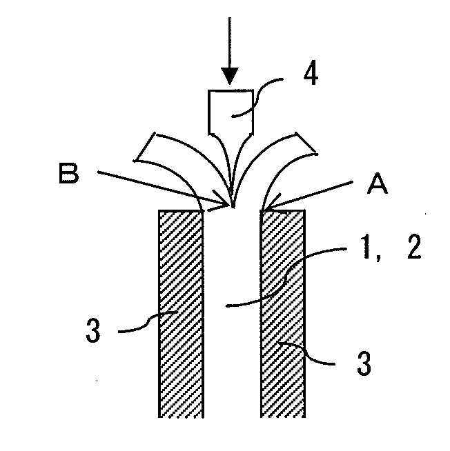
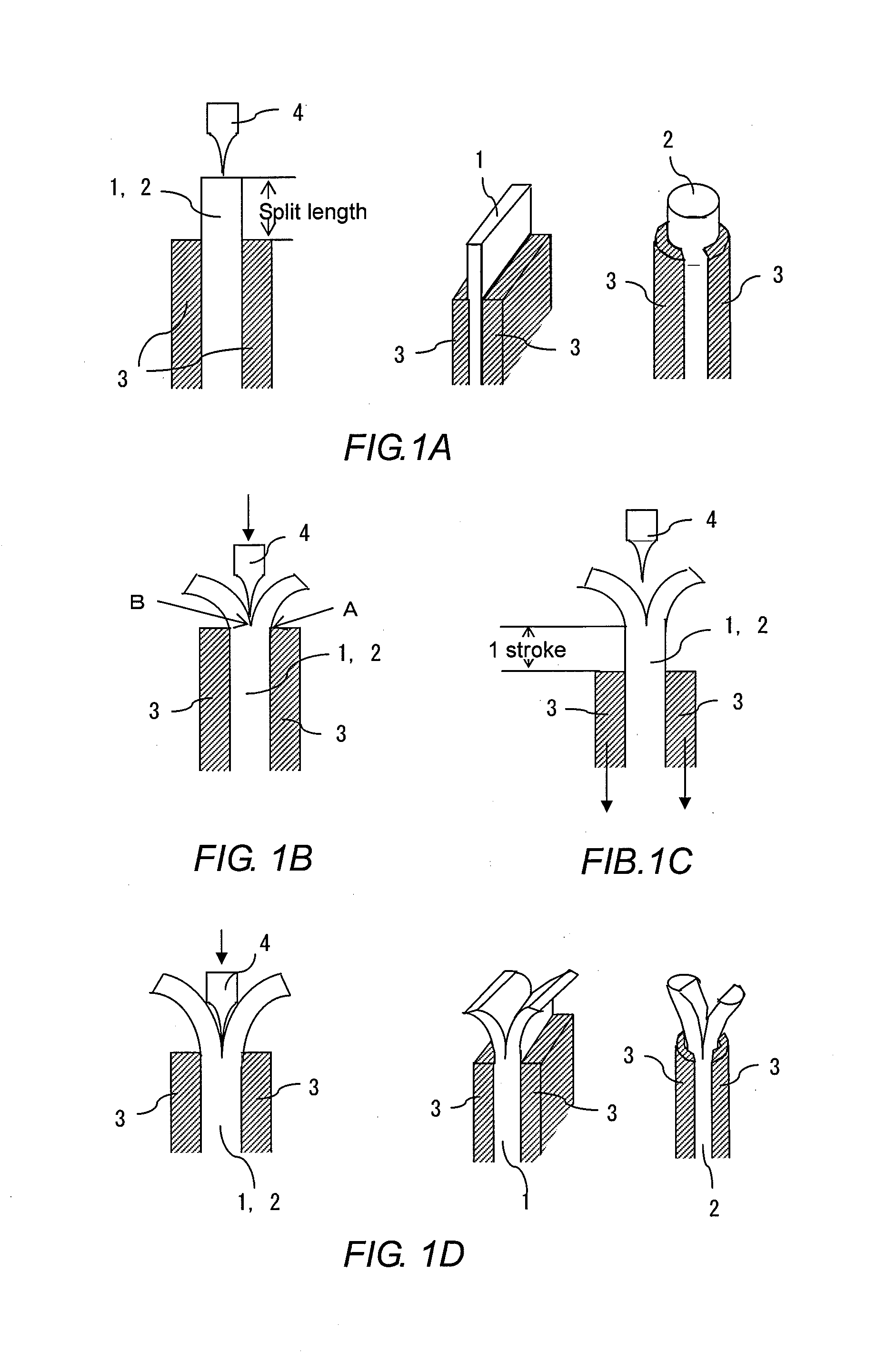
[0058]FIGS. 1A to 1D are an explanatory illustration of steps of the press-splitting in the first embodiment of the method for splitting the end part of a metal plate 1, or a metal rod 2, according to the present invention, wherein a slitting punch 4 is used while moving a clamping device 3. As FIGS. 1A to 1D illustrate, the end splitting method in this embodiment comprises the steps of: securing the metal plate 1 or, the metal rod 2, by pinching with the clamping device 3 (FIG. 1A); performing press-splitting applying the slitting punch 4 on the face of one end of the metal plate 1, or the metal rod 2 (FIG. 1B); moving the clamping device 3 to the split-desired position and securing again the metal plate 1, or the metal rod 2, by pinching with the clamping device 3 to secure (FIG. 1C); and applying the slitting punch 4 on the cleft of the split portion to advance splitting by the press-splitting (FIG. 1D). The steps illustrated in FIGS. 1C and 1D are repeated until the split length...

second embodiment

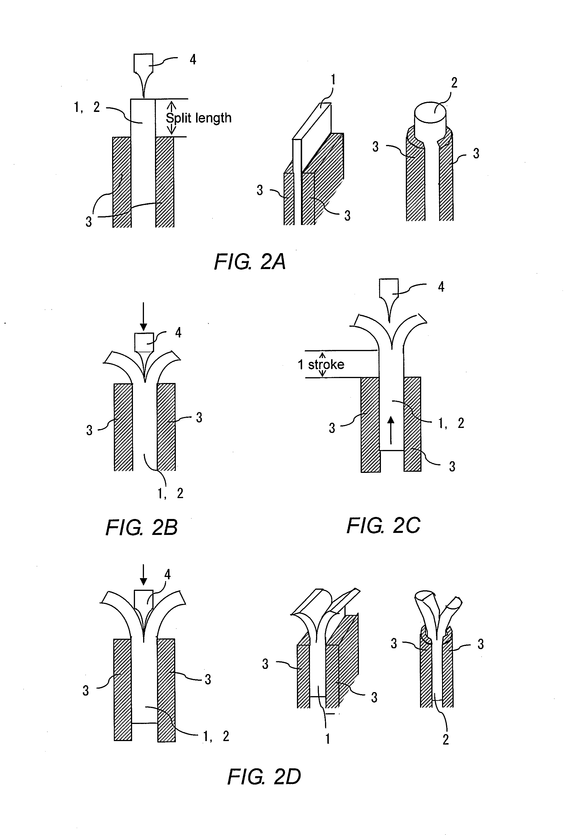
[0064]FIGS. 2A to 2D are an explanatory illustration of steps of the press-splitting in the second embodiment of the method for splitting the end part of a metal plate 1, or a metal rod 2, according to the present invention, wherein a slitting punch 4 is used while moving the metal plate 1, or the metal rod 2. In this embodiment, securing the metal plate 2, or the metal rod 2, by pinching with a clamping device 3 (FIG. 2A) and performing press-splitting applying the slitting punch 4 on the face of one end of the metal plate 1, or the metal rod 2 (FIG. 2B), are the same steps as those in the first embodiment illustrated in FIGS. 1A and 1B. The difference from the steps indicated in FIGS. 1A and 1B is that the metal plate 1, or the metal rod 2, is moved instead of moving the clamping device 3. The embodiment employs a step, in which the metal plate 1, or the metal rod 2, is secured again by pinching with the clamping device 3 after the metal plate 1, or the metal rod 2, is moved to th...

third embodiment

[0066]FIGS. 3A to 3D are an explanatory illustration of steps of the press-splitting in the third embodiment of the method for splitting the end part of a metal plate 1, or a metal rod 2, according to the present invention, wherein a cleaving punch 5 is used while moving a clamping device 3. As FIGS. 3A to 3D illustrate, the end splitting method in this embodiment comprises the steps of: securing the metal plate 1, or the metal rod 2, by pinching with the clamping device 3 (FIG. 3A); performing press-splitting, applying the cleaving punch 5 on the face of one end of the metal plate 1, or the metal rod 2, along one face of the clamping device 3 on one side (FIG. 3B); moving one side of the clamping device 3, which is disposed on the other side of the face on which the clamping device 3 stated above is arranged, to the split-desired position and securing again the metal plate 1, or the metal rod 2, by pinching with the clamping device 3 to secure (FIG. 3C); and applying the cleaving p...


PUM

PropertyMeasurementUnit
lengthaaaaaaaaaa
speedaaaaaaaaaa
speedaaaaaaaaaa

Abstract

Provided are a method for splitting longitudinally an end part of a metal plate or a metal rod having a rectangular, polygonal, or elliptical shape, in which the length of incision in the split portion can be freely adjusted and smooth split face can be formed; a metal part manufactured by such method; and a method for bonding such metal part. The present invention is characterized by the process comprising the steps of securing a metal plate by pinching both sides thereof with a clamping device, or securing a metal rod by pinching at least two opposite-facing portions on the periphery thereof with a clamping device; splitting longitudinally by slitting or cleaving the metal plate, or the metal rod, by pressing a slitting punch or a cleaving punch against the face of one end of the metal plate, or the metal rod; and advancing the splitting further by repeating the same operation of pressing the same punch stated above against the cleft of the splitting; and is characterized further in that, in each time of the press-splitting operation, the position of the clamping device on at least one side is moved in advance of the next pressing by a stroke corresponding to the distance from one end of the metal plate, or the metal rod, to the distal end of a split-desired portion.

Description

TECHNICAL FIELD[0001]The present invention relates to a method for splitting an end part of a metal plate having any of a rectangular, polygonal, or elliptical shape, or an end part of a metal rod having a cross-section of any of a circular, elliptical, rectangular, or polygonal shape, in the longitudinal direction with respect to the metal plate or the metal rod, wherein the method permits free-adjustment of the length of incision in the split portion and provides smooth and even split faces. The present invention further relates to a metal part manufactured by the invented end splitting method and a method for bonding so manufactured parts.BACKGROUND OF THE INVENTION[0002]Until now in the field of sheet metal V-pulleys and sheet metal brake shoes, a manufacturing method such that a rotating slitting roller or a rotating cleaving roller is pressed against the outer peripheral portion of a circular metal material to split such portion into two parts is known (see Patent literatures ...

Claims


Application Information

Patent Timeline
Patent Type & Authority Applications(United States)
IPC IPC(8): B26D3/28B23K31/02B32B38/00
CPCB26D3/28B23K31/02B32B38/0004B21D39/00B21F13/00B23D23/02B23D31/00B23D33/08B21J5/068F16B5/0096F16B17/004Y10T29/49826Y10T29/49948Y10T29/49956Y10T156/1064Y10T428/12229Y10T428/12375Y10T428/12389Y10T428/24612Y10T83/0267
Inventor SEKI, MASAKATSU
Owner SEKI PRESS
Why Eureka
Try Eureka