
Ferrite core built-in connector

a built-in connector and ferrite core technology, which is applied in the direction of core/yokes, magnetic bodies, coupling device connections, etc., can solve the problems of reducing the strength of the connector housing and damage to the ferrite core, and achieves the effect of improving the noise removal characteristic of the ferrite core built-in connector, high removal effect, and high removal

Active Publication Date: 2014-11-27
AUTONETWORKS TECH LTD +2
View PDF4 Cites 12 Cited by
  • Summary
  • Abstract
  • Description
  • Claims
  • Application Information

AI Technical Summary

Benefits of technology

The patent relates to an improved ferrite core design for a connector that helps remove noise components. The ferrite core is fit to each tab terminal and a retaining wall prevents detachment. The ferrite core has different frequency ranges where noise components can be removed, and can be made to high removal effects for removing specific types of noise. The connector housing is formed with molding projections that cover side surfaces of the ferrite core to create clearances between the ferrite core and the connector housing. This prevents a contractile force from acting on the ferrite core after the connector housing is molded, and there is no need to provide an opening in the connector housing to reduce its strength.

Problems solved by technology

However, the ferrite core may be damaged by a compressive stress due to a contractile force during resin curing.
However, an opening formed in the connector housing as described above, reducing the strength of the connector housing.

Method used


Image

  • Ferrite core built-in connector
  • Ferrite core built-in connector
  • Ferrite core built-in connector

Examples


Embodiment Construction

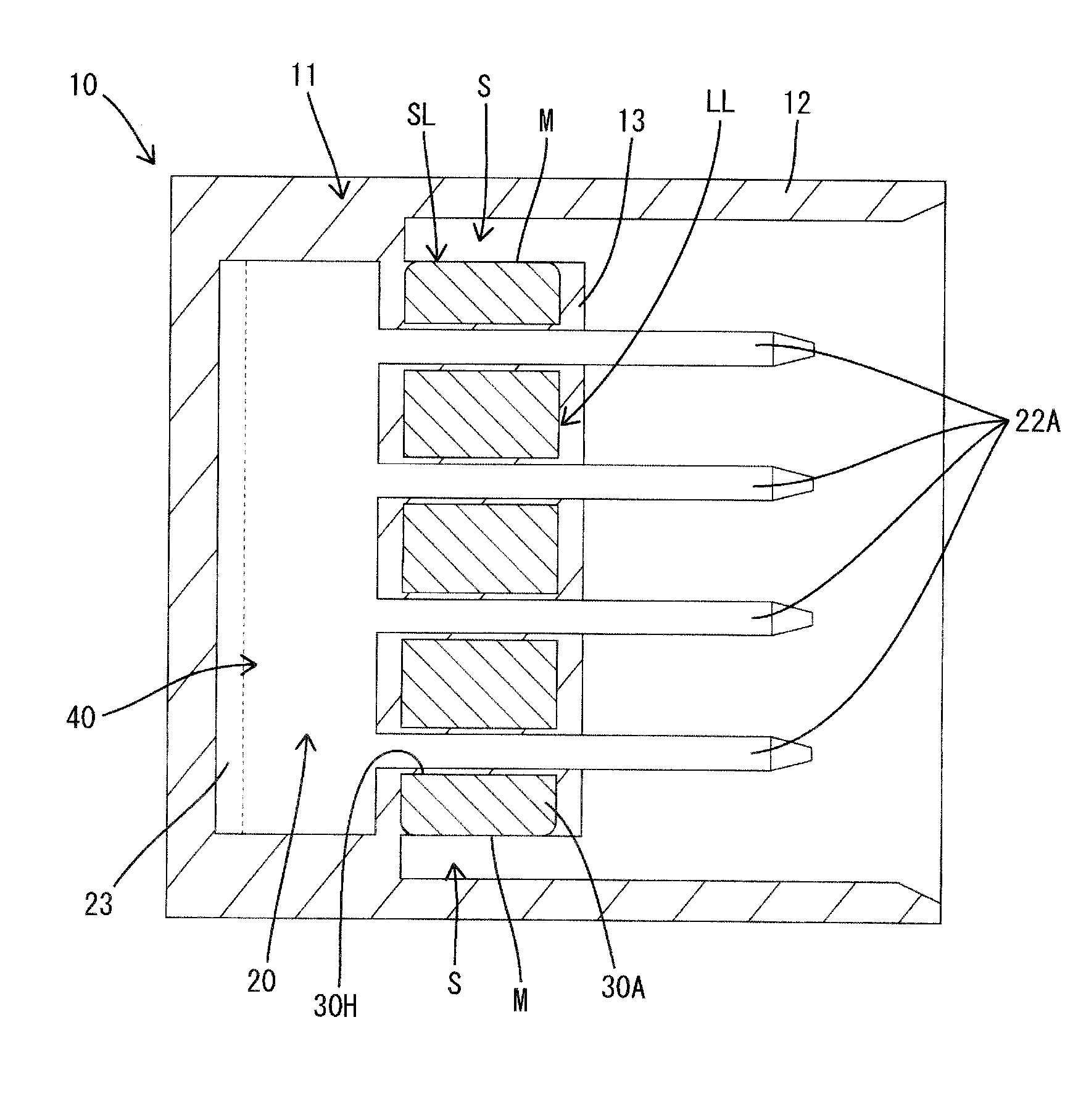
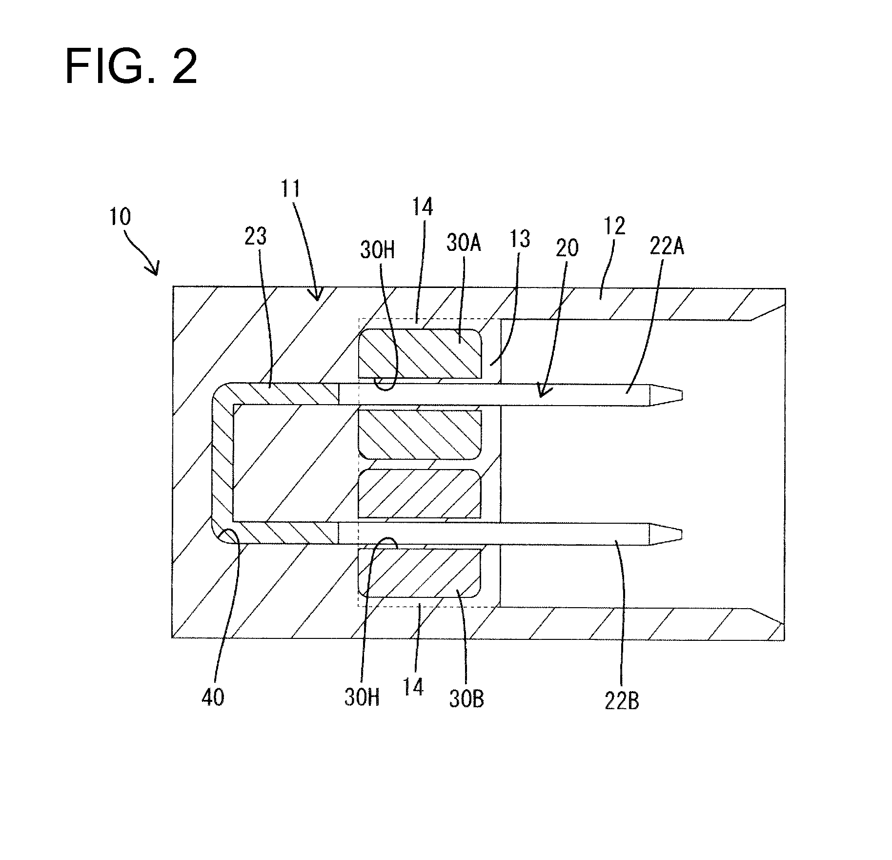
[0022]A ferrite core built-in connector 10 (hereinafter, merely referred to as a connector 10) of this embodiment includes a busbar terminal 20, first and second types of ferrite cores 30A, 30B for noise removal, and a connector housing 11. Note that, in the following description, right and left sides of FIG. 3 are referred to as front and rear sides concerning a front-back direction.

[0023]The connector housing 11 is made e.g. of synthetic resin and includes, as shown in FIG. 3, a rectangular tubular receptacle 12 having a front opening 11H and a circuit unit 40 incorporated integrally in the receptacle 12 by insert molding. The circuit unit 40 comprises the busbar terminal 20 and the ferrite cores 30A, 30B.

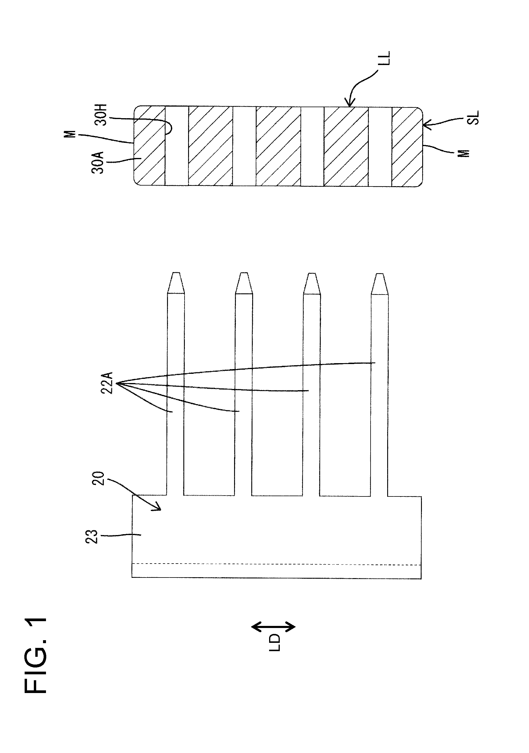
[0024]The busbar terminal 20 is formed by cutting or punching a metal conductive plate material, such as copper alloy, and applying bending, folding and / or embossing and the like to a cut- or punched-out piece. The busbar terminal 20 has tab-shaped tab terminals 22A, 22B and a ba...


PUM


Abstract

A connector includes ferrite cores (30A, 30B) with through holes (30H). A terminal fitting (20) has tab terminals (22A, 22B) inserted into the respective through holes (30H) to define input and output portions and a base (23) couples end parts of the respective tab terminals (22A, 22B) to each other. A connector housing (11) is molded to surround the ferrite cores (30A, 30B) and the terminal fitting (20) and is connectable to a mating connector housing. The ferrite cores (30A, 30B) include long sides LL and short sides SL. Clearances S are defined between side surfaces M located on the opposite short sides SL of the ferrite cores (30A, 30B) and facing surfaces of the connector housing (11), thereby separating the side surfaces M from the facing surfaces.

Description

BACKGROUND[0001]1. Field of the Invention[0002]The invention relates to a ferrite core built-in connector.[0003]2. Description of the Related Art[0004]Some known connectors control an electronic component installed in an automotive vehicle by CAN (Control Area Network) communication and have a block-shaped ferrite core fit to a busbar terminal projecting in a connecting direction to remove noise current that adversely affects signal transmission.[0005]A connector could be formed by insert molding a ferrite core and a busbar terminal in a connector housing made of synthetic resin. However, the ferrite core may be damaged by a compressive stress due to a contractile force during resin curing. JP 2010-118212 discloses a technique for preventing damage of a ferrite core due to a compressive stress by forming an opening in a connector housing and exposing opposite longitudinal end surfaces of the ferrite core, to which the compressive stress is greatest.[0006]However, an opening formed i...

Claims


Application Information

Patent Timeline
IPC IPC(8): H01R13/6588
CPCH01R13/6588H01R13/7193H01R31/08H01R2201/26H01F5/003H01F17/045H01F27/292H01F41/04H01F1/344H01F41/10H01F3/08H01F17/04H01F41/005H01F27/324H01F27/255H01F2017/048
Inventor AIZAWA, TAKESHI
Owner AUTONETWORKS TECH LTD
Learn More