Acoustic wave detection probe and photoacoustic measurement apparatus provided with the same

a detection probe and photoacoustic technology, which is applied in the direction of instruments, optical elements, diagnostic recording/measure, etc., can solve the imbalance in the amount of energy of light traveling through each optical fiber of the bundle fiber, and the inability to ensure the homogeneity of the energy profile of the light outputted from the fused bundle fiber, so as to eliminate the imbalance in the amount of energy of light traveling and transmit high-energy light

Active Publication Date: 2014-11-27
FUJIFILM CORP
View PDF6 Cites 15 Cited by
  • Summary
  • Abstract
  • Description
  • Claims
  • Application Information

AI Technical Summary

Benefits of technology

[0008]In Japanese Unexamined Patent Publication No. 2004-193267, all that is required is to simply transmit light, so that it is not necessary to ensure the homogeneity of the energy profile of exiting light. In the photoacoustic measurements, however, the homogeneity of the energy profile of the light actually projected to the subject is required from the viewpoint of reconstructing quality photoacoustic signals, in addition to the transmission of high energy light. For that purpose, it is important to eliminate the imbalance in the amount of energy between each light traveling through each optical fiber of the bundle fiber.
[0009]The present invention has been developed in response to the aforementioned requirement, and it is an object of the present invention to provide an acoustic wave detection probe and photoacoustic measurement apparatus capable of transmitting high energy light and eliminating imbalance in the amount of energy between each light traveling through each of a plurality of optical fibers in photoacoustic measurements.
[0032]The acoustic wave detection probe and the photoacoustic measurement apparatus according to the present invention are characterized in that the light guide section includes a homogenizer that flat-tops an energy profile of the measuring light entered therein, a light condensing member that condenses the measuring light transmitted through the homogenizer, and a bundle fiber which includes a plurality of optical fibers and is disposed such that the measuring light transmitted through the light condensing member enters from an entrance end of the bundle fiber. This allows the flat-topped laser light to dividedly enter each optical fiber in the bundle fiber and damage to the end face of the bundle fiber due to local energy exceeding damage threshold energy to be prevented to a large extent. As a result of this, it is possible to transmit high energy light and eliminate imbalance in the amount of energy of light traveling through each of a plurality of optical fibers in photoacoustic measurements.

Problems solved by technology

The use of the method described in Japanese Unexamined Patent Publication No. 2004-193267 in the photoacoustic measurements, however, poses a problem that the homogeneity of the energy profile of the light outputted from the fused bundle fiber cannot be ensured.
Then, it is presumed that there is an imbalance in the amount of energy of light traveling through each optical fiber of the bundle fiber.

Method used


Image

  • Acoustic wave detection probe and photoacoustic measurement apparatus provided with the same
  • Acoustic wave detection probe and photoacoustic measurement apparatus provided with the same
  • Acoustic wave detection probe and photoacoustic measurement apparatus provided with the same

Examples


third embodiment

[Third Embodiment of Acoustic Wave Detection Probe]

[0095]Next, a third embodiment of the acoustic wave detection probe will be described. The probe of the present embodiment differs from the first embodiment in that it projects light guided by the bundle fiber 42 via a light guide plate. Therefore, components identical to those of the first embodiment will not be elaborated upon further here unless otherwise specifically required.

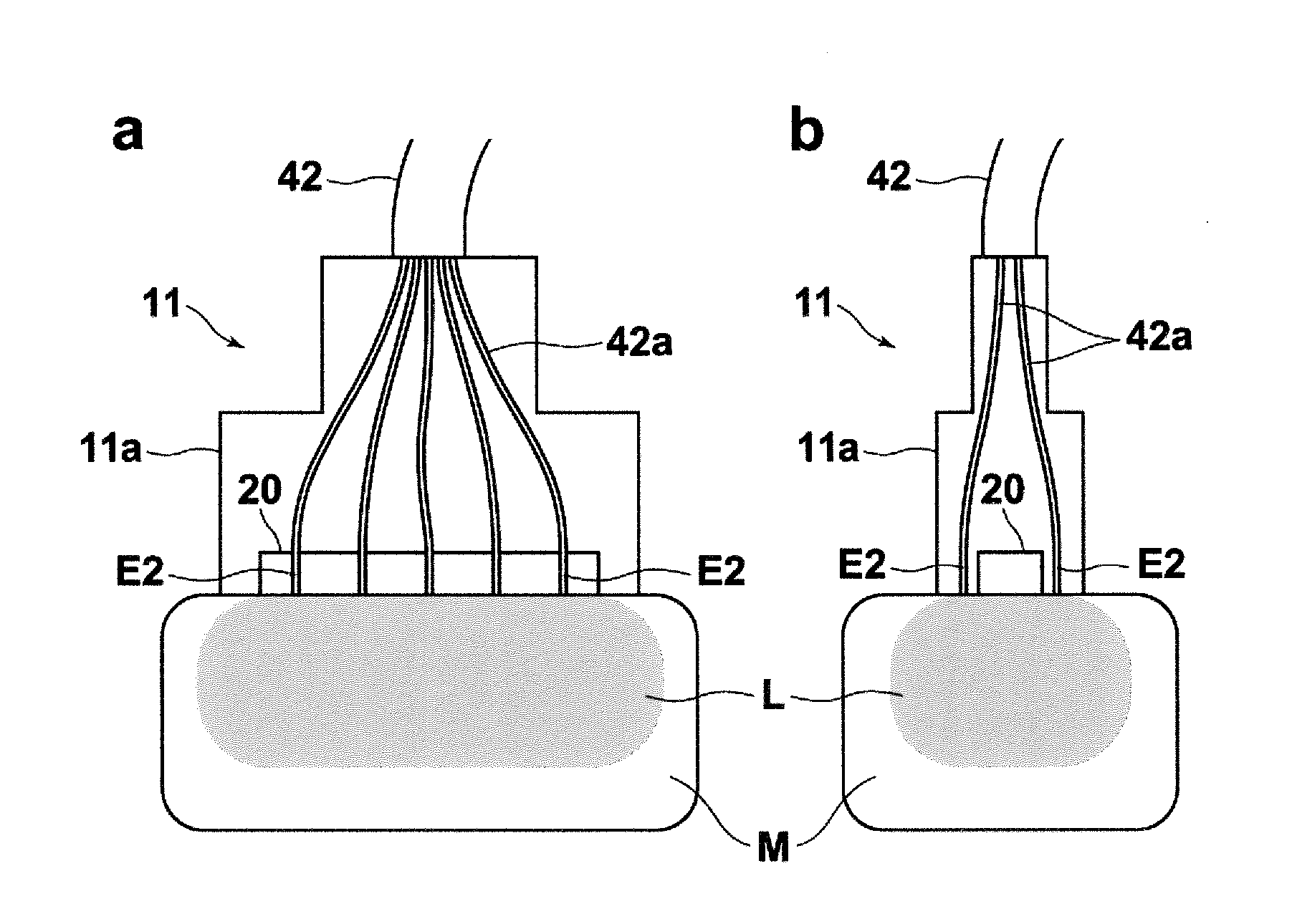
[0096]FIG. 10 illustrates light guide plate configuration examples. FIG. 11 is a schematic view illustrating the arrangement of the acoustic wave transducer, the optical fibers, and the light guide plate in the probe of the present embodiment, in which a is a cross-sectional view viewed from the front and b is a cross-sectional view viewed from the side.

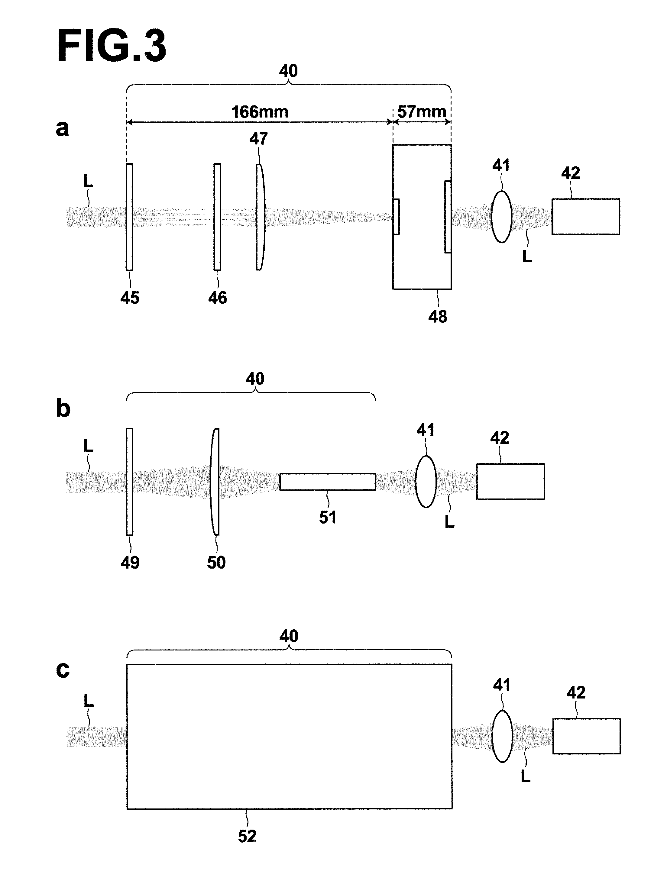
[0097]The probe 11 according to the present embodiment includes a light guide section which is formed of the homogenizer, the light condensing member, the fusion processed bundle fiber 42, and a light guide ...

first embodiment

[First Embodiment of Photoacoustic Measurement Apparatus]

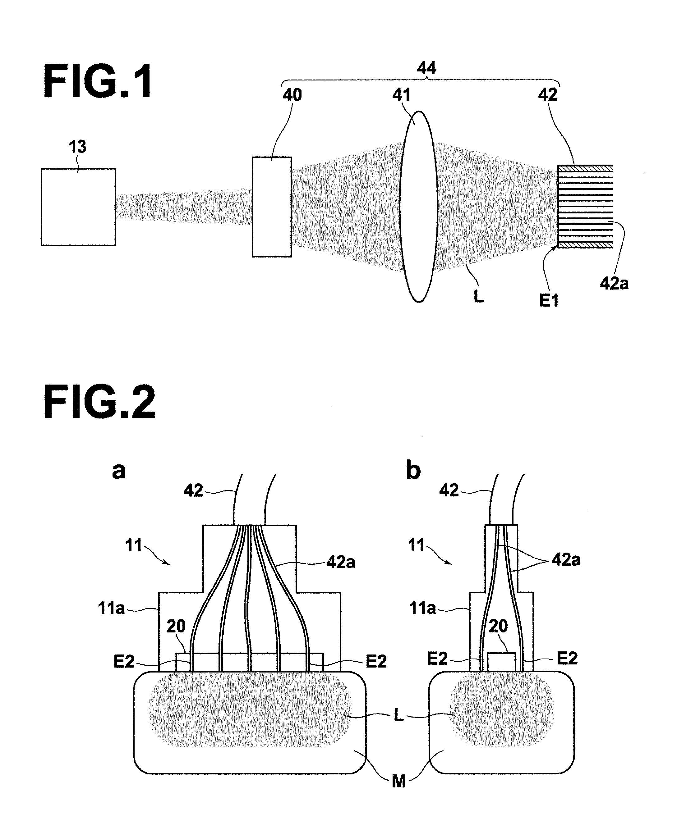
[0118]Next, a first embodiment of photoacoustic measurement apparatus will be described. In the present embodiment, a detailed description will be made of a case in which the photoacoustic measurement apparatus is a photoacoustic image generation apparatus that generates a photoacoustic image based on photoacoustic signals. FIG. 21 is a block diagram of the photoacoustic image generation apparatus 10 of the present embodiment, illustrating the configuration thereof.

[0119]The photoacoustic image generation apparatus 10 of the present embodiment includes a probe 11 according to the present invention, an ultrasonic unit 12, a laser unit 13, an image display means 14, and an input means 16.

[0120]The laser unit 13 corresponds to the light source of the present invention and outputs, for example, laser light L as measuring light to be projected onto a subject M. The laser unit 13 is configured to output the laser light L, for exampl...

second embodiment

[Second Embodiment of Photoacoustic Measurement Apparatus]

[0139]A second embodiment of photoacoustic measurement apparatus will be described next. Also in the present embodiment, a detailed description will be made of a case in which the photoacoustic measurement apparatus is a photoacoustic image generation apparatus. FIG. 22 is a block diagram of the photoacoustic image generation apparatus 10 of the present embodiment, illustrating the configuration thereof. The present embodiment differs from the first embodiment in that it generates an ultrasonic image in addition to the photoacoustic image. Therefore, the detailed description of the components identical to those of the first embodiment is omitted unless otherwise specifically required.

[0140]The photoacoustic image generation apparatus 10 of the present embodiment includes a probe 11 according to the present invention, an ultrasonic unit 12, a laser unit 13, an image display means 14, and an input means 16, as in the first embo...


PUM

PropertyMeasurementUnit
diffusion angleaaaaaaaaaa
Diffusion Angleaaaaaaaaaa

Abstract

In an acoustic wave detection probe provided with a light guide section that guides measuring light such that the measuring light is outputted toward a subject and an acoustic wave transducer that detects a photoacoustic wave generated in the subject by the projection of the measuring light, the light guide section includes a homogenizer that flat-tops an energy profile of the measuring light entered from the upstream side of the optical system, a light condensing member that condenses the measuring light transmitted through the homogenizer, and a. bundle fiber which includes a plurality of optical fibers and is disposed such that the measuring light transmitted through the light condensing member enters from an entrance end of the bundle fiber.

Description

CROSS-REFERENCE TO RELATED APPLICATIONS[0001]This application is a Continuation of PCT International Application No. PCT / JP2013 / 001182 filed on Feb. 27, 2013, which claims priority under 35 U.S.C. §119 (a) to Japanese Patent Application No. 2012-043595 filed on Feb. 29, 2012 and Japanese Patent Application No. 2013-033053 filed on Feb. 22, 2013, the contents of which are hereby expressly incorporated herein by reference in their entirety.TECHNICAL FIELD [0002]The present invention relates to a probe to be applied to a measurement target to detect an acoustic wave, and a photoacoustic measurement apparatus.BACKGROUND ART [0003]The photoacoustic spectroscopy is a method in which a pulsed light having a predetermined wavelength (e.g., wavelength range of visible light, near infrared light, or mid-infrared light) is projected onto a subject and a photoacoustic wave, which is an elastic wave generated as a result of absorption of the energy of the pulsed light by a specific substance in ...

Claims


Application Information

Patent Timeline
Patent Type & Authority Applications(United States)
IPC IPC(8): G01N29/24A61B5/00
CPCA61B5/0095G01N2291/02466G01N29/2418G01N29/2462G02B27/0927A61B2090/306A61B2576/00A61B90/30A61B5/0097
Inventor IRISAWA, KAKU
Owner FUJIFILM CORP
Why Eureka
Try Eureka