
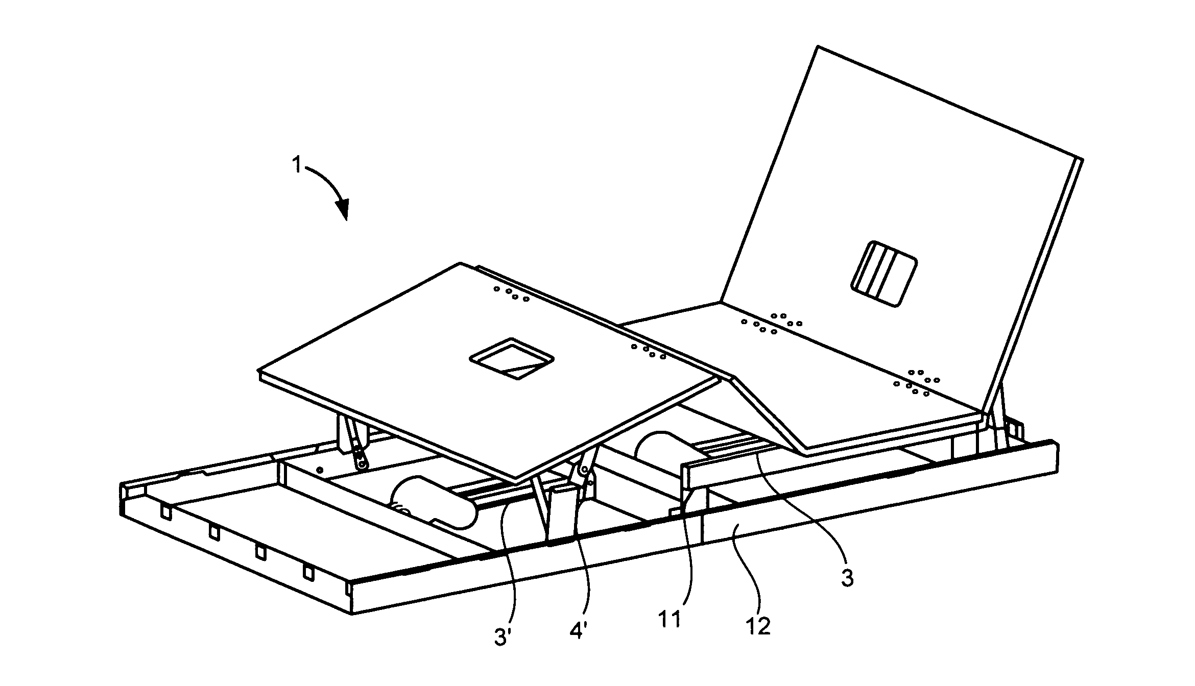
Electric motorized bed

a motorized bed and electric technology, applied in the field of adjustable electric beds, can solve the problems of limiting the sliding motor to protect the sliding motor from damage, and achieve the effects of reducing the number of sliding motors

Inactive Publication Date: 2014-12-04
KEESON TECH CORP LTD
View PDF11 Cites 35 Cited by
  • Summary
  • Abstract
  • Description
  • Claims
  • Application Information

AI Technical Summary

Benefits of technology

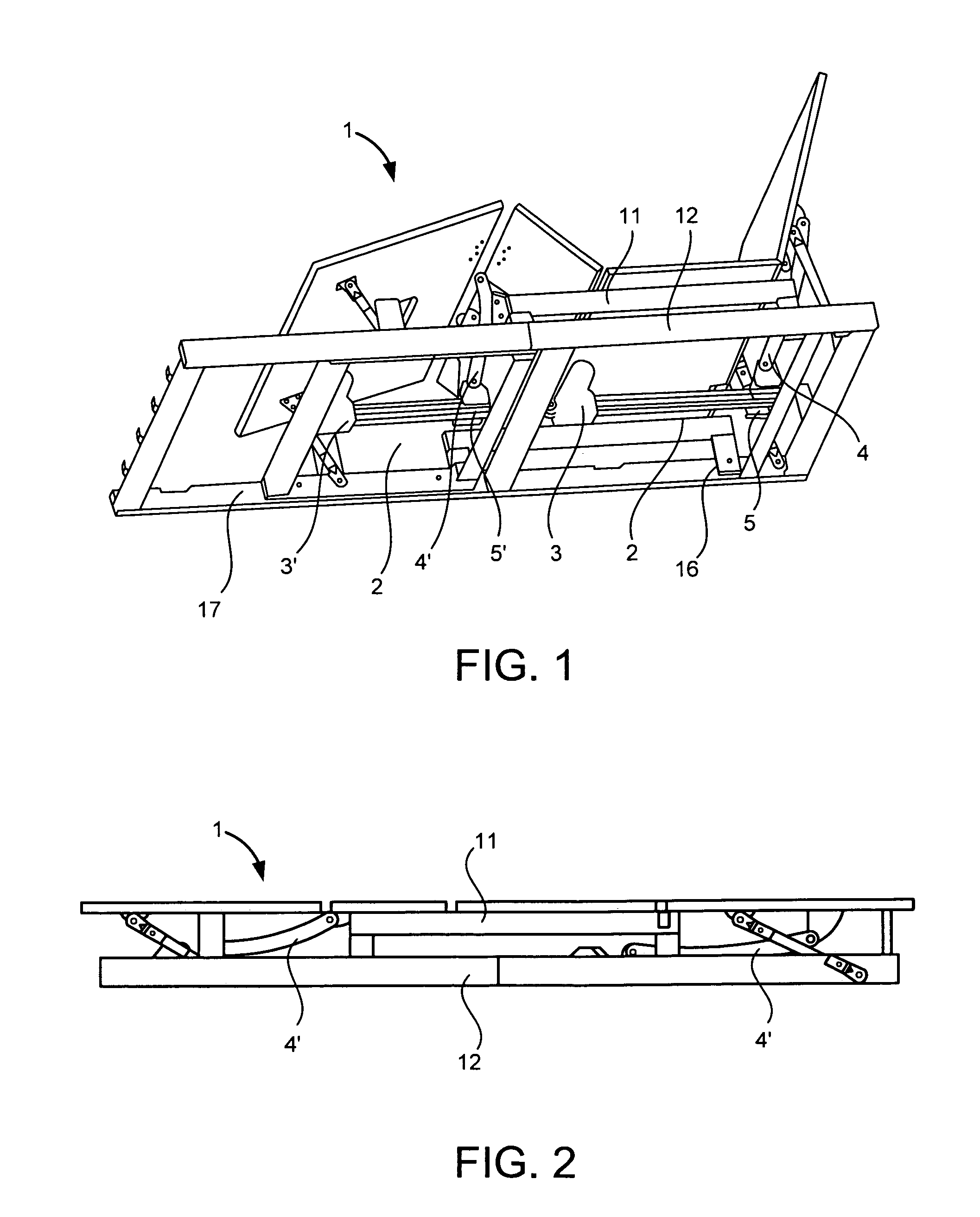
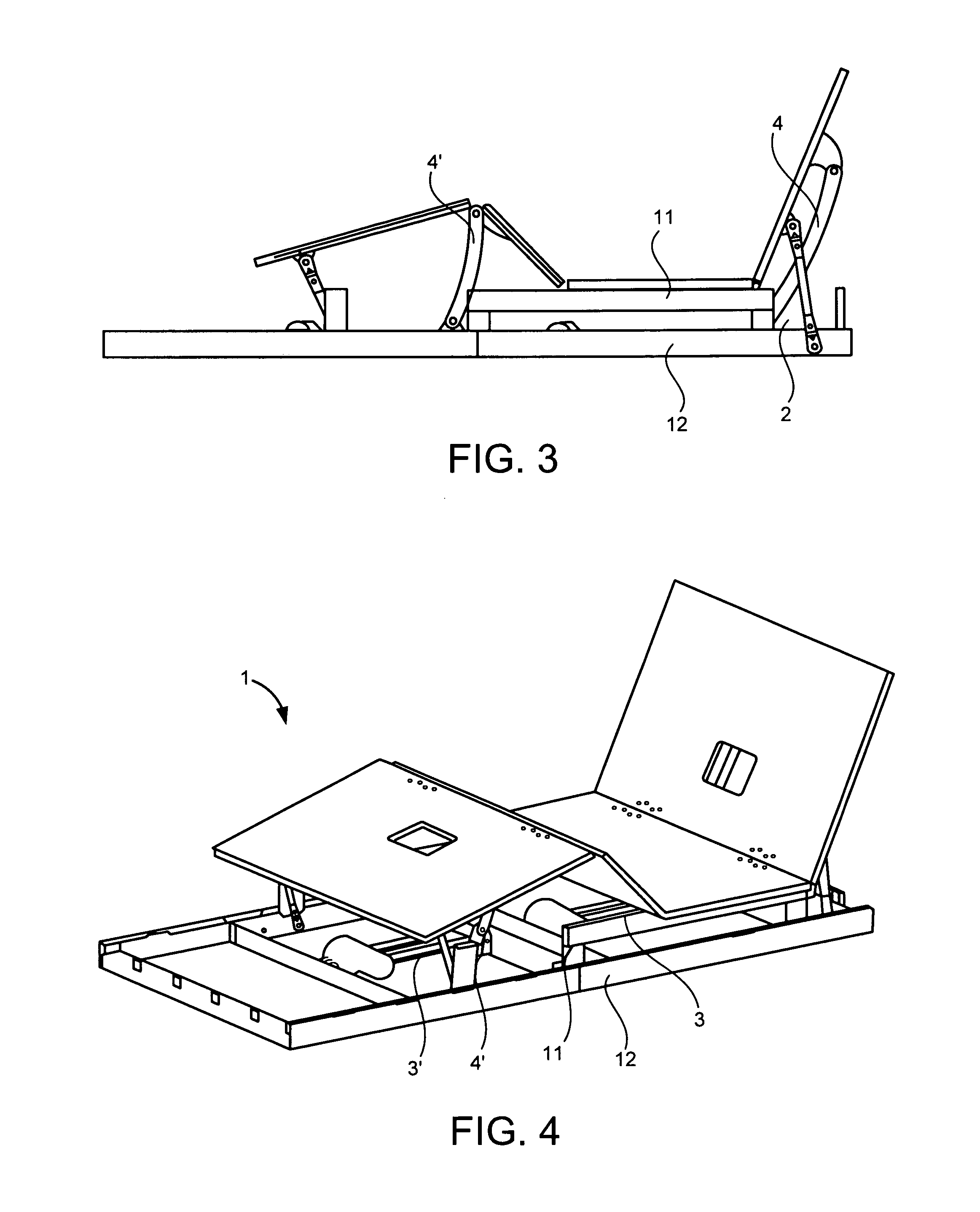
The invention provides a new electric bed that solves problems of traditional electric beds such as fatigue damage and increased pressure on the bearing unit. The new electric bed contributes to pressure dispersion and increases service life. The sliding motor system has a position sensor to sense the slider position when outside of the immobile position and in the mobile position. The electric bed frame is designed to eliminate difficulties in packing, transport and handling and seeks to save packing and transport costs, reduce labor requirements, facilitate handling in a house, and improve application performance of the electric bed. The linear actuator is replaced with the slider motor and the pressure previously applied at the hinge joint between the linear actuator and the bed frame can be dispersed at two fixing points to greatly reduce pressure applied on all parts. This reduction of pressure seeks to prolong the service life of all parts and improve the performance of the electric bed. Additionally, the strength requirement of materials for many parts can be lowered due to the pressure reduction so that materials with lower strength and cost can be selected to manufacture the relevant parts.

Problems solved by technology

The slider can be limited to protect the slider motor from being damaged.

Method used


Image

  • Electric motorized bed
  • Electric motorized bed
  • Electric motorized bed

Examples


Embodiment Construction

[0073]As seen in the figures, several boards have hinge connection to the frame. The boards support the mattress and include the head board which is also called the back board because the backboard supports the back and head and the headboard supports the head and back. A fixed board is sometimes called the seat board as a user sits on the seat board. A thigh board then supports the user's thighs and a leg board or calf board supports the user's legs and feet. The leg board is also called a foot board because the leg board supports the feet. The present invention has the back board also called the headboard attached to the lower frame in a hinged connection at a backboard connection rod. The back board, seat board, thigh board, and calf board are also mounted to and supported by the upper frame 101. The upper frame is supported by the lower frame, and the lower frame rests on the ground. The upper frame has wheels that roll on the first guide rail 123 and the second guide rail 124 o...


PUM


Abstract

An electric motorized bed has a bedframe, and multiple bed boards. The bedframe includes an upper bedframe and a lower bedframe. The upper bedframe and lower bedframe are connected by a guide rail. Multiple bed boards are connected to each other and one bedboard is connected to the bedframe. The slider motor system has a connecting rod. The slider motor systems two sides are connected to the lower bedframe. The slider motor system has a slider connecting with one of the bed boards using a connecting rod. The slider motor system has a slider that can move between a nonmovable position and a movable position. In the nonmovable position there is another bed board positioned horizontally. In the movable position, another bedboard is positioned to be capable of being raised and lowered. Another bedboard can be positioned at any location between the horizontal position and a vertical moving position.

Description

[0001]This application claims priority from and is a Paris Convention Treaty of non-provisional applications: People's Republic of China utility model patent application 201320559726.X entitled Electric Movable Bed, filed Sep. 10, 2013, by inventor Xu, Jianchun; and People's Republic of China utility model patent application 201320399032.4 entitled Electric Movable Bed; filed Jul. 5, 2013 by inventor Xu, Jianchun, the disclosures of which are incorporated herein by reference.FIELD OF THE INVENTION[0002]The field of the invention is in the field of adjustable electric beds.BACKGROUND[0003]Electric beds are now widely used as rates of obesity and elder care have increased. The bed board of a common electric bed includes multiple boards: a head board, a fixed board that can be a seat board, a leg board, and a foot board. The boards are connected in series by hinges, and are lifted by a motor driving the boards to meet various postural requirements during use.[0004]An upper bed frame an...

Claims


Application Information

Patent Timeline
IPC IPC(8): A47C20/04A61G7/018A61G7/015
CPCA47C20/041A61G7/018A61G7/015
Inventor XU, JIANCHUN
Owner KEESON TECH CORP LTD
Learn More