
Nebulizer systems and methods

a nebulizer and system technology, applied in the field of nebulizer systems and methods, can solve the problems of droplets passing through the mesh or membrane, nebulizers suffer from a variety of drawbacks, waste, and excessive dead volum

Active Publication Date: 2014-12-04
GENERAL ELECTRIC CO
View PDF11 Cites 20 Cited by
  • Summary
  • Abstract
  • Description
  • Claims
  • Application Information

AI Technical Summary

Benefits of technology

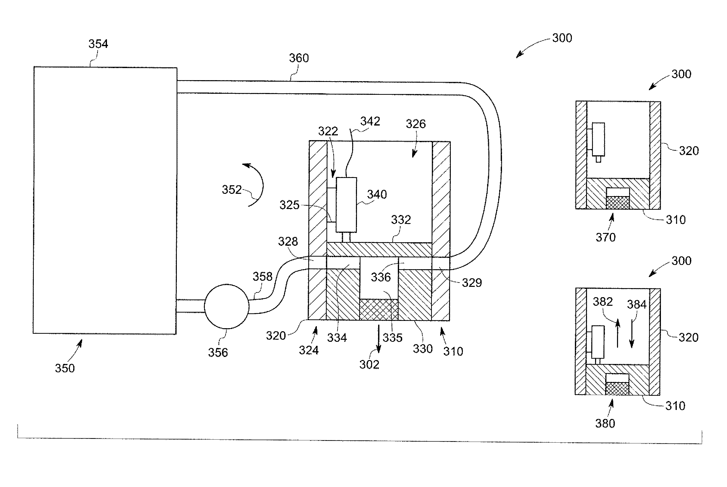
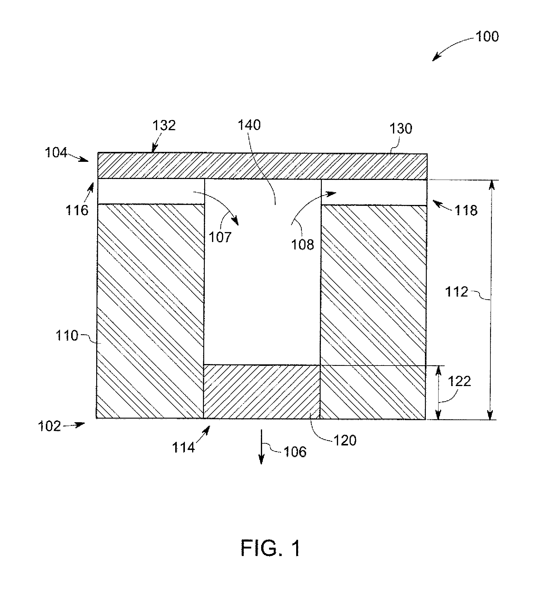
The patent describes a nebulizer assembly that can be attached to an ultrasonic actuator. The assembly has a base plate, a porous mesh member, and a cover member. The base plate has an opening that allows ultrasonic vibrations to pass through and vibrate the porous mesh member. The porous mesh member is designed to pass a nebulized fluid therethrough. The cover member is placed on the other side of the base plate and defines a cavity that holds the fluid to be nebulized. In this way, the ultrasonic actuator can be used to vibrate the nebulizer to create small droplets of fluid that can be inhaled. The technical effect of this invention is that it provides a simple and effective way to produce nebulized fluid for delivery to the respiratory system.

Problems solved by technology

Vibration of the piezoelectric element causes a vibration of the mesh or membrane and results in the passage of droplets through the mesh or membrane.
Such nebulizers, however, suffer from a variety of drawbacks.
For example, such nebulizers typically utilize a generally large reservoir, resulting in excessive dead volume and waste.
Further, as the volume in the reservoir changes, the rate of mist production may become difficult to measure and / or control.
Further still, the piezoelectric element may be affixed to the mesh or membrane, resulting in high costs of replacement (as the piezoelectric element and mesh are disposed together) and / or contamination of the piezoelectric element.
Further still, such nebulizers may typically operate in only one given orientation, limiting the versatility or flexibility of use of the device.

Method used


Image

  • Nebulizer systems and methods
  • Nebulizer systems and methods
  • Nebulizer systems and methods

Examples


Embodiment Construction

[0012]Various embodiments will be better understood when read in conjunction with the appended drawings. To the extent that the figures illustrate diagrams of the functional blocks of various embodiments, the functional blocks are not necessarily indicative of the division between componentry. Thus, for example, one or more of the functional blocks (e.g., processors, controllers or memories) may be implemented in a single piece of hardware (e.g., a general purpose signal processor or random access memory, hard disk, or the like) or multiple pieces of hardware. Similarly, any programs may be stand-alone programs, may be incorporated as subroutines in an operating system, may be functions in an installed software package, and the like. It should be understood that the various embodiments are not limited to the arrangements and instrumentality shown in the drawings.

[0013]As used herein, the terms “system,”“unit,” or “module” may include a hardware and / or software system that operates t...


PUM


Abstract

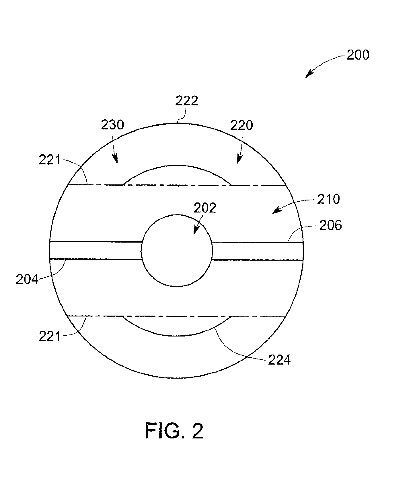
A nebulizer assembly configured for removable attachment to an ultrasonic actuator includes a base plate portion, a porous mesh member, and a cover member. The base plate portion includes an opening extending therethrough, and is substantially rigid such that ultrasonic vibrations from the ultrasonic actuator may be transmitted through the base plate portion to the porous mesh member to vibrate the porous mesh member. The porous mesh member is configured for passage therethrough of a nebulized fluid, and is disposed in the opening of the base plate portion proximate a fluid emission side of the nebulizer assembly. The cover member is disposed on a second side of the nebulizer assembly opposite the fluid emission side. The cover member covers the opening and defines a cavity between the cover member and the porous mesh member. The cavity is configured to retain a fluid to be nebulized.

Description

BACKGROUND[0001]Nebulizers may be employed to deliver a fluid as a mist. For example, in medical applications, nebulizers may be used as drug delivery devices for delivering medication to a patient in the form of a mist that may be inhaled by the patient. As another example, water (e.g., heated water) may be delivered from a nebulizer to a patient to be inhaled for humidification. Various nebulizers may utilize oxygen, ultrasonic power (e.g., vibrations), and / or compressed air to provide droplets (e.g., aerosol droplets or mist) from solutions or suspensions. The droplets may then be inhaled, for example using a facemask operably connected to the nebulizer.[0002]For example, certain nebulizers may employ ultrasonic vibrations to provide a mist. In some nebulizers, an electronic oscillator is used to generate a high frequency ultrasonic wave, which in turn causes a mechanical vibration of a piezoelectric element. The vibrating piezoelectric element, if in contact with a liquid (e.g.,...

Claims


Application Information

Patent Timeline
IPC IPC(8): A61M15/00
CPCA61M15/0028A61M15/0085A61M11/005A61M2016/0027A61M2016/0033B05B17/06
Inventor SESHADRI, SATYANARAYANANBALLER, MARKO KLAUSRAKWAL, DINESH
Owner GENERAL ELECTRIC CO
Learn More