
Low-consumption, amr-type, integrated magnetoresistor

a magnetoresistor and low-consumption technology, applied in the field of low-consumption integrated magnetoresistors, can solve the problems of high consumption of the magnetoresistor b>1/b>, the reduction of the duration of the set/reset pulse down to the values indicated above is not always sufficient, and the high value of the set/reset current is not easy to obtain. , to achieve the effect of increasing the amplitude of the magnetic field

Active Publication Date: 2014-12-04
STMICROELECTRONICS INT NV
View PDF14 Cites 26 Cited by
  • Summary
  • Abstract
  • Description
  • Claims
  • Application Information

AI Technical Summary

Benefits of technology

This patent describes a structure for an AMR magnetoresistive sensor that includes a magnetic-field concentration layer. This layer helps to increase the magnetic field acting on the sensor during a refresh operation, which results in better magnetization of the sensor during read operations. Overall, this structure improves the performance of the magnetoresistive sensor.

Problems solved by technology

However, the refresh operation calls for high currents for the set / reset operations and thus involves a high consumption of the magnetoresistor 1.
However, miniaturization of devices and integration of an ever-increasing number of functions in portable devices require a further reduction of the power consumption levels so that the reduction of duration of the set / reset pulses down to the values indicated above is not always sufficient.
Moreover, the high value of the set / reset currents is not easy to obtain.
In fact, for this purpose, the driving circuit (generally provided as ASIC—Application-Specific Integrated Circuit) requires the presence of power MOS transistors that are able to carry the required high currents, with consequent increase in the overall dimensions and costs.
However, these requirements clash with the desire of scaling for small packaged sensors of reduced dimensions (e.g., 1.5×1.5 mm2).
Manufacture of the capacitor as an external component on the application board involves further costs and implementation difficulties.
Another problem linked to the presence of high pulses in the device resides in that these pulses may capacitively couple to the digital part, driving spurious resets thereon, with undesirable effects on operation of the device.
Another problem in known magnetoresistors lies in that, if they are immersed in a high stray field having the same direction as magnetization, and thus opposite direction as the field generated by the set / reset coil, the initial set / reset condition may be cancelled out, causing errors in the measurements.
This problem involves a reduction of the maximum magnetic field that can be detected by the magnetoresistor.
This reduction is particularly undesirable in the case of magnetoresistive sensors mounted in cellphones and other mobile devices, operating in environments where increasingly strong stray magnetic fields are present.

Method used


Image

  • Low-consumption, amr-type, integrated magnetoresistor
  • Low-consumption, amr-type, integrated magnetoresistor
  • Low-consumption, amr-type, integrated magnetoresistor

Examples


Embodiment Construction

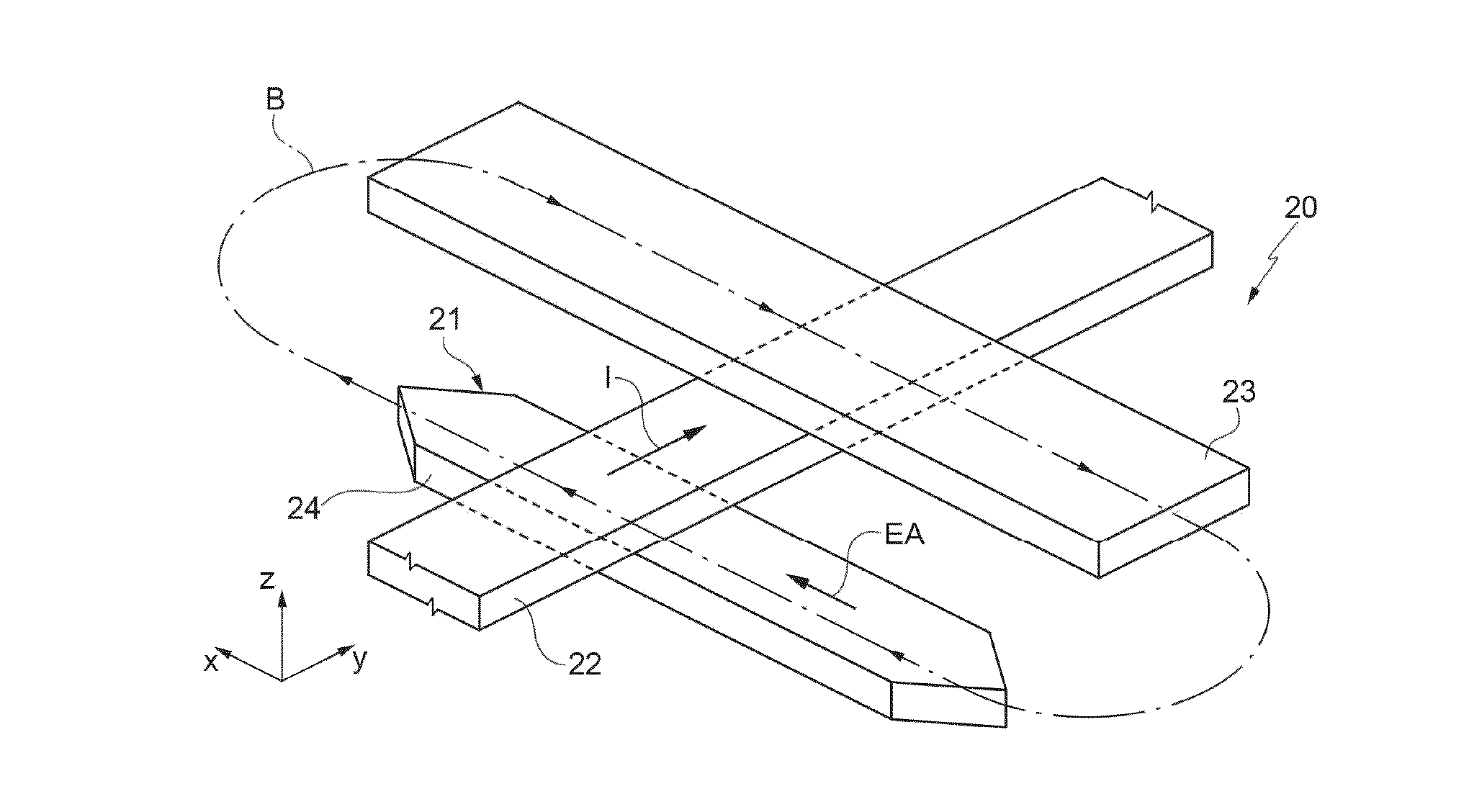
[0041]FIG. 6 is a schematic illustration of a portion of one embodiment of the present magnetoresistive sensor.

[0042]In detail, the magnetoresistive sensor of FIG. 6, designated by 20, comprises a magnetoresistor 21, a set / reset coil 22, and a concentrating region 23, which are arranged in a stack. In turn, the magnetoresistor 21 comprises a magnetoresistive strip 24 having an elongated shape in the direction of the easy axis EA, and barber poles (here not shown). In particular, the magnetoresistive strip 21 is made of magnetoresistive material, such as, for example, permalloy (a ferromagnetic alloy containing iron and nickel) and has a shape elongated in the direction of the easy axis EA. The set / reset coil 22, of conductive material, such as aluminium, is arranged between the magnetoresistive strip 21 and the concentrating region 23 and has at least one portion (portion represented) that extends in a second transverse direction, in particular perpendicular to the magnetoresistive ...


PUM


Abstract

An integrated magnetoresistive sensor (20; 30; 40) of an AMR (Anisotropic Magneto Resistance) type, formed by a magnetoresistive strip (24) of ferromagnetic material and having an elongated shape with a preferential magnetization direction (EA). A set / reset coil (22) has a stretch (34a, 34b), which extends over and transversely to the magnetoresistive strip. A concentrating region (23), also of ferromagnetic material, extends over the stretch of the set / reset coil so as to form a magnetic circuit for the field generated by the set / reset coil during steps of refresh and maintenance of magnetization of the magnetoresistive coil.

Description

CROSS REFERENCE TO RELATED APPLICATIONS[0001]This application claims the priority benefit of Italian Patent Application No. TO2013A000436, filed May 29, 2013, and which application is hereby incorporated by reference to the maximum extent allowable by law.BACKGROUND[0002]1. Technical Field[0003]The present disclosure relates to a low-consumption integrated magnetoresistor of an AMR (Anisotropic MagnetoResistance) type.[0004]2. Discussion of the Related Art[0005]Magnetic-field AMR sensors are used in a plurality of applications and systems, for example in compasses, in systems for detecting ferromagnetic characteristics, in the detection of currents, and in a wide range of other applications, by virtue of their capacity of detecting natural magnetic fields (for example, the Earth's magnetic field) and magnetic fields generated by electrical components (such as electrical or electronic devices and lines run by electric current).[0006]As is known, the above magnetoresistive sensors exp...

Claims


Application Information

Patent Timeline
IPC IPC(8): G01R33/09H01L27/22H01L43/02
CPCG01R33/096H01L27/22H01L43/02G01R33/0011H10B61/00H10N59/00H10N50/80
Inventor PACI, DARIO
Owner STMICROELECTRONICS INT NV
Learn More