
Light emitting display device and method for fabricating the same

a technology of light emitting display and light emitting layer, which is applied in the manufacture of electrode systems, electric discharge tubes/lamps, discharge tubes luminescnet screens, etc., can solve the problems of polluting the light emitting layer, degrading high diffusivity of the insulation film, so as to improve the display quality of the light emitting display device, effective prevention of polluting, and effective reduction of the light emitting efficiency

Active Publication Date: 2014-12-04
SAMSUNG DISPLAY CO LTD
View PDF2 Cites 13 Cited by
  • Summary
  • Abstract
  • Description
  • Claims
  • Application Information

AI Technical Summary

Benefits of technology

This patent is about a new light emitting display device that prevents pollution of the light emitting layer by fluorine. Flurine can be diffused from an insulating film to the light emitting layer, causing lowered light emitting efficiency and degraded display quality. The patent proposes a blocking film that prevents fluorine from being diffused, resulting in improved display quality and lifespan. The blocking film also prevents color mixing during the process of providing the light emitting layer.

Problems solved by technology

In such organic light emitting device, fluorine included in the insulating film has high diffusivity, such that fluorine may be diffused into a light emitting layer that is disposed inside an opening and thereby pollute the light emitting layer.
When the light emitting layer is polluted, the light emitting efficiency of the light emitting layer may be lowered, thereby degrading the display quality of the light emitting display device, and the light emitting layer may be deteriorated, thereby lowering the lifespan of the light emitting display device.

Method used


Image

  • Light emitting display device and method for fabricating the same
  • Light emitting display device and method for fabricating the same
  • Light emitting display device and method for fabricating the same

Examples


Embodiment Construction

[0027]The invention will be described more fully hereinafter with reference to the accompanying drawings, in which embodiments of the invention are shown. This invention may, however, be embodied in many different forms, and should not be construed as limited to the embodiments set forth herein. Rather, these embodiments are provided so that this disclosure will be thorough and complete, and will fully convey the scope of the invention to those skilled in the art. Like reference numerals refer to like elements throughout.

[0028]It will be understood that when an element or layer is referred to as being “on”, “connected to” or “coupled to” another element or layer, it can be directly on, connected or coupled to the other element or layer or intervening elements or layers may be present. In contrast, when an element is referred to as being “directly on,”“directly connected to” or “directly coupled to” another element or layer, there are no intervening elements or layers present. Like n...


PUM


Abstract

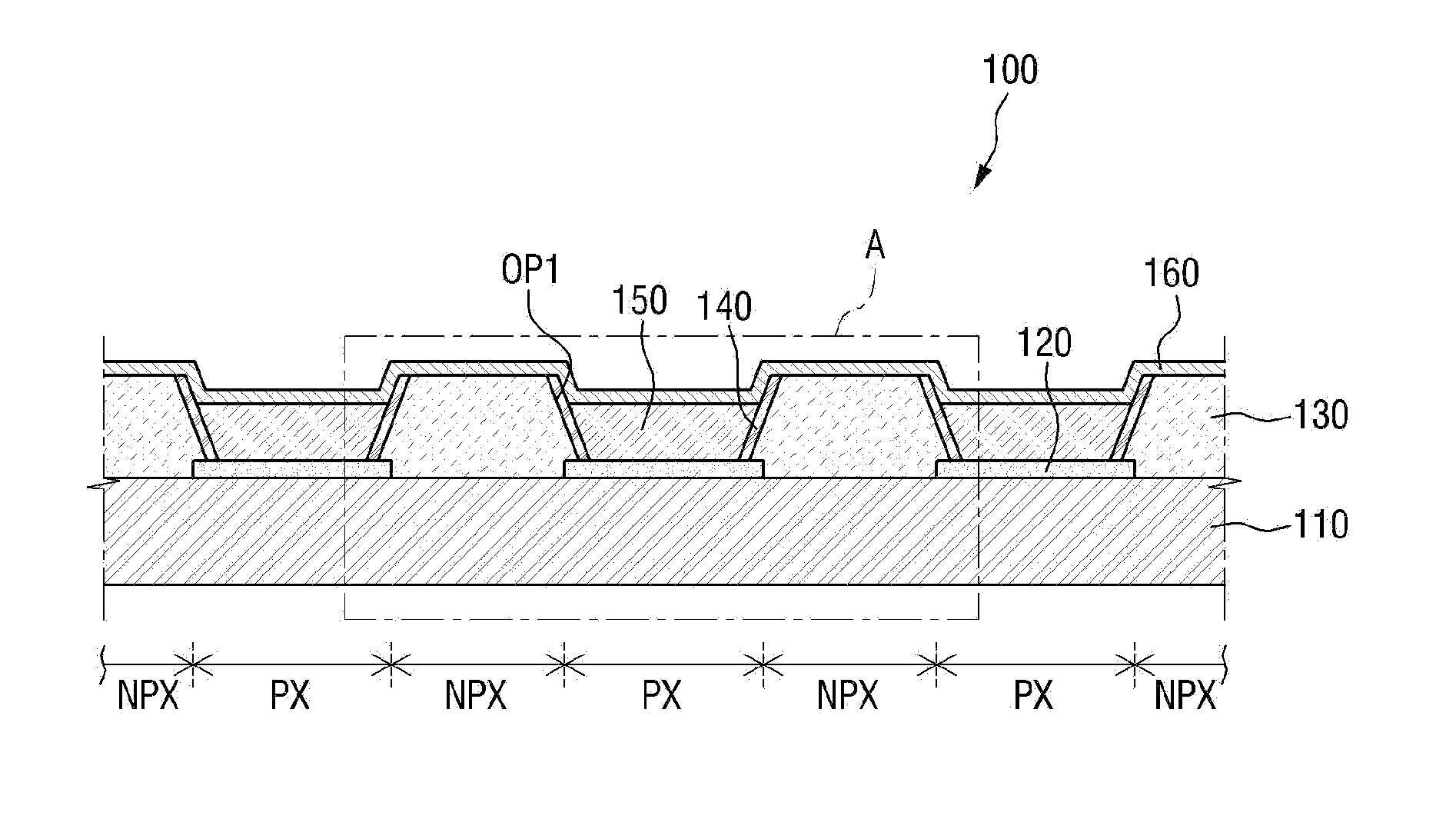
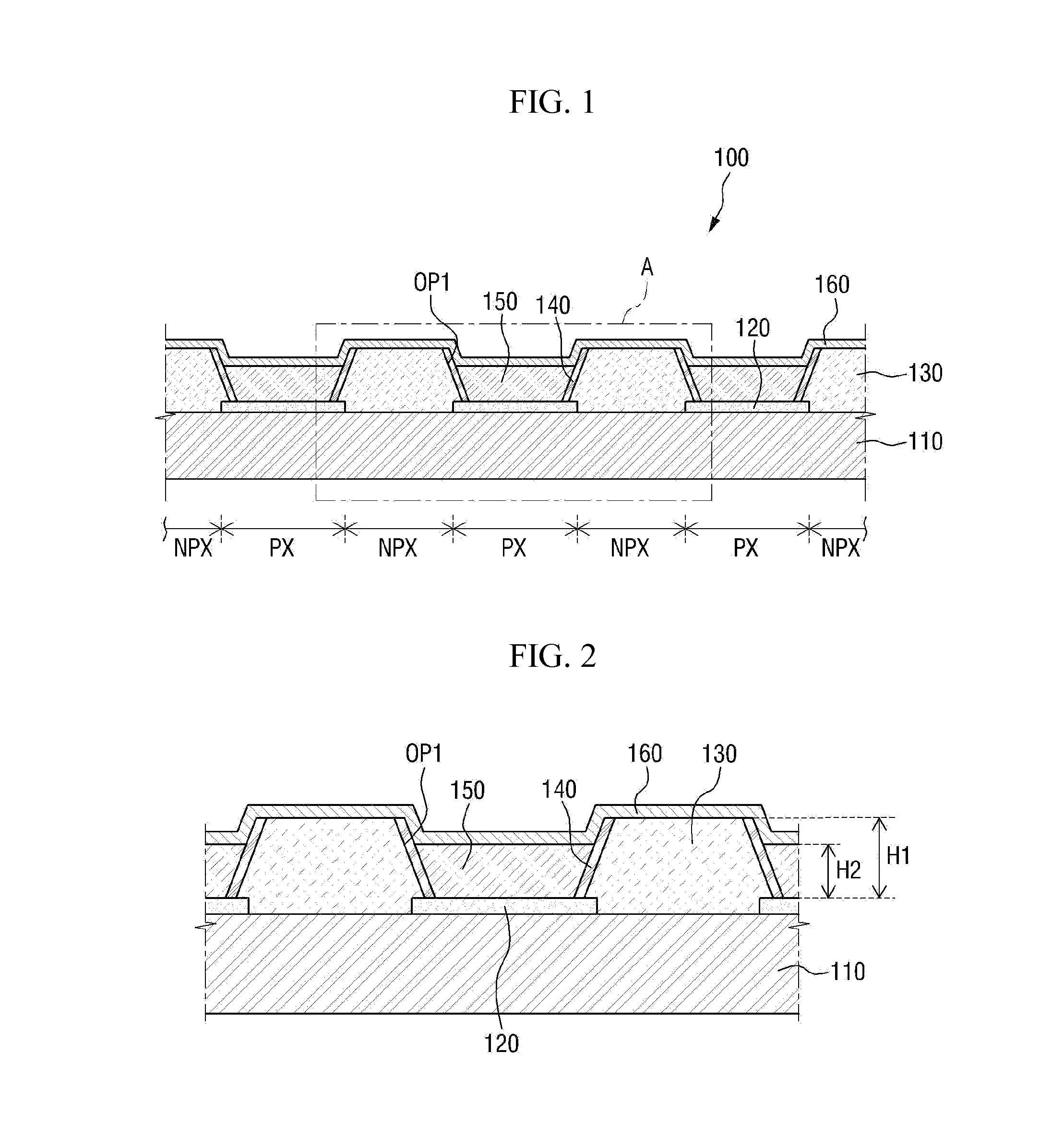
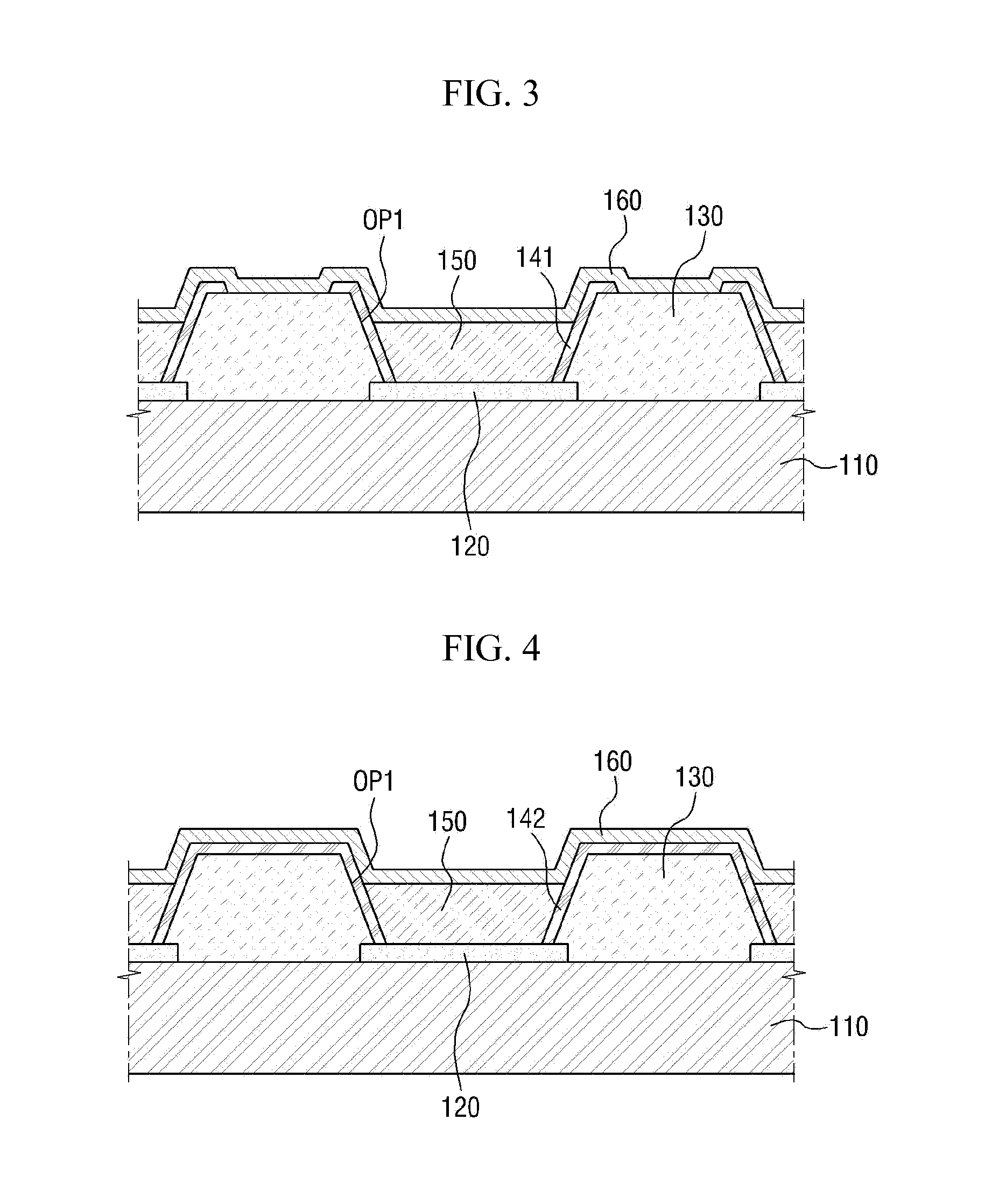
A light emitting display device includes: a substrate; a first electrode disposed on the substrate in each pixel area; an insulating film disposed on the substrate, where a first opening, which exposes the first electrode, is defined in the insulating film; a blocking film disposed on a side surface of the insulating film, which defines the first opening; a light emitting layer disposed in the first opening and on the first electrode, where the light emitting layer is in contact with the blocking film; and a second electrode disposed on the light emitting layer.

Description

[0001]This application claims priority to Korean Patent Application No. 10-2013-0060516, filed on May 28, 2013, and all the benefits accruing therefrom under 35 U.S.C. §119, the contents of which in their entireties are herein incorporated by reference.BACKGROUND[0002]1. Field[0003]Exemplary embodiments of the invention relates to a light emitting display device and a method for fabricating the light emitting display device.[0004]2. Description of the Prior Art[0005]Typically, a flat display device may be classified into a light emitting type and a light receiving type. A light emitting type display device may include a flat cathode ray tube, a plasma display panel, an electroluminescence device or a light emitting diode. A light receiving type display device may include a liquid crystal display. Among light emitting type display devices, the electroluminescence device typically has a wide viewing angle, high contrast and high response speed, and has been noticed as the next-generat...

Claims


Application Information

Patent Timeline
IPC IPC(8): H05B33/12H05B33/10
CPCH05B33/10H05B33/12H10K59/122H10K71/135H10K59/1201H10K59/30H10K59/123H10K59/124H10K59/126H10K50/844
Inventor YOON, JOO SUN
Owner SAMSUNG DISPLAY CO LTD
Learn More