
Visible light receiving method and apparatus using the same

a technology which is applied in the field of receiving method and receiving apparatus, can solve the problems of difficult to precisely extract visible light transmission data from image data, difficult to accurately extract visible light transmission data in overexposed state, and inability to extract received data at high speed, so as to achieve the effect of easy receiving and high speed

Active Publication Date: 2014-12-04
UNIVERLINK
View PDF4 Cites 10 Cited by
  • Summary
  • Abstract
  • Description
  • Claims
  • Application Information

AI Technical Summary

Benefits of technology

This patent describes a method and apparatus for receiving information signals through visible light communication. The invention allows for faster processing and more efficient data transmission compared to conventional methods. By using a camera to capture visible light signals, the invention can easily receive information transmitted for visible light communication. The technical effect of this patent is to provide a convenient and efficient means for visible light communication.

Problems solved by technology

Therefore, even if the image data photographed by the camera is subjected to image processing, it is extremely difficult to precisely extract visible light transmission data contained in the image data in an overexposed state even for an image processing technology of a microcomputer operating at high speed.
Further, when photographing a visible light, even in the case where a photographed image is not brought into an overexposed state, because a contour and the like of the image are contained as noise in visible light transmission data, it is difficult to precisely extract the visible light transmission data from the image data.
Therefore, in the visible light receiving apparatus using a conventional camera, in addition to the fact that it is extremely difficult to extract receiving data from an image including a contour of an object photographed by the camera, or image data in an overexposed state by image processing, it is impossible to extract received data at high speed because transmission data transmitted through visible light communication (for example, in the case of a data transmission speed of 4.8 Kbps, a signal at a frequency of about 9.6 kHz) is acquired at a speed of 1 sample for one frame.

Method used


Image

  • Visible light receiving method and apparatus using the same
  • Visible light receiving method and apparatus using the same
  • Visible light receiving method and apparatus using the same

Examples


Embodiment Construction

[0051]Hereinafter, the present invention will be described on the basis of an embodiment shown in the drawings. In addition, the invention is not limited to the embodiment. Any modifications within the requirements of Claims or equivalents relating to the requirements should be contained in the scope of Claims.

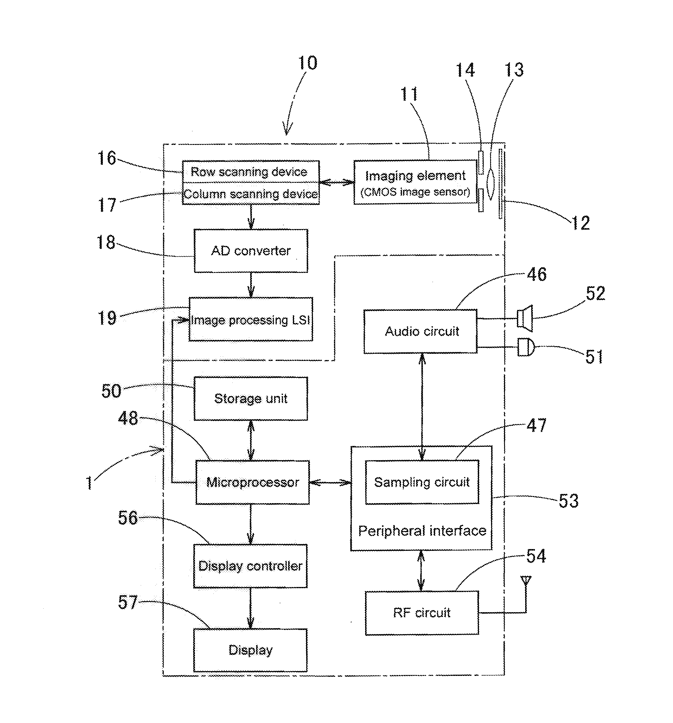
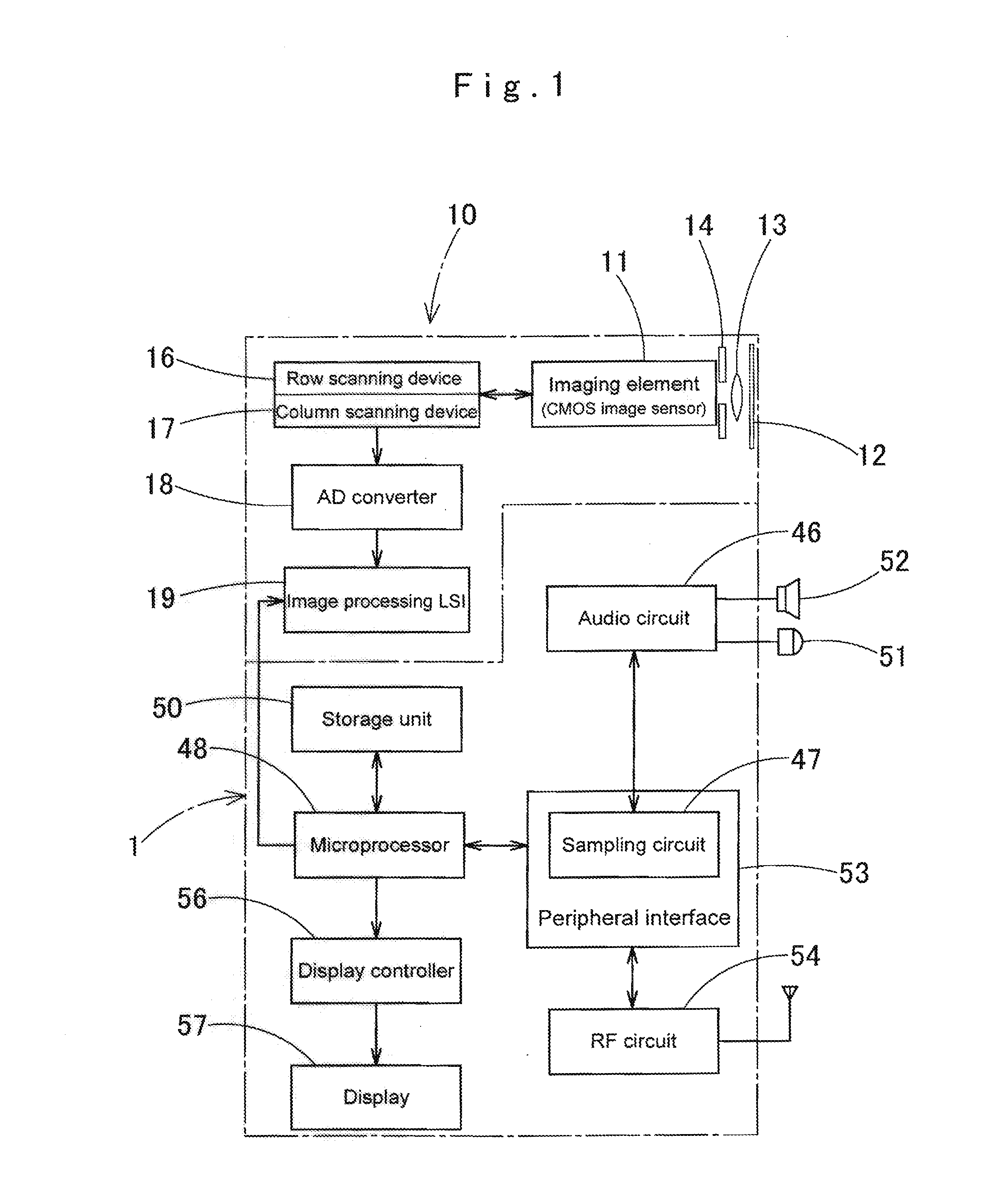
[0052]FIG. 1 shows a schematic configuration block diagram of a portable terminal 1 equipped with a visible light receiving apparatus that receives a visible light for visible light communication.

[0053]The portable terminal 1 is a terminal device in which a camera (digital camera) 10 such as a mobile telephone is mounted, that photographs a still image or a moving image by operating a function switch and the like in a camera mode of the portable terminal 1. When photographing a still image or a moving image, the portable terminal 1 receives an information signal of a visible light transmitted for visible light communication.

[0054]As shown in FIG. 1, in an optical incident part...


PUM


Abstract

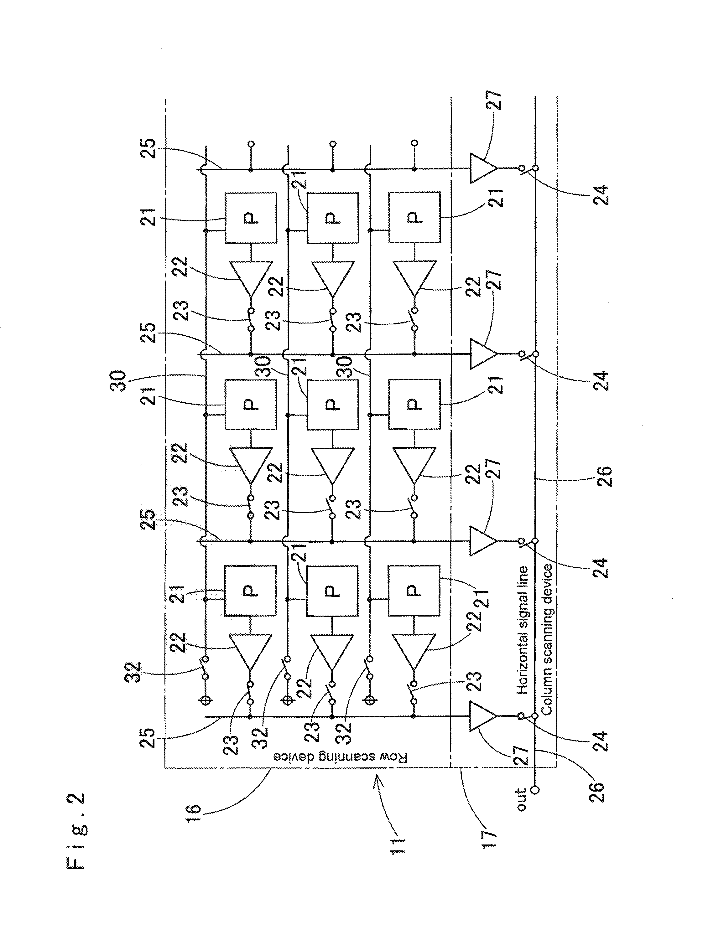
A visible light is photographed through an optical diffusion filter with a camera of a portable terminal. The camera includes a pixel amplifier sequential output type imaging element in which electric charges generated in respective pixels are amplified by respective pixel amplifiers, to output imaging signals in sequence from the respective pixel amplifiers. A striped pattern based on an information signal is generated in the column direction or row direction in the imaging element, in a photographed optically-diffused image. The information signal is extracted to be demodulated on the basis of a state of generation of the striped pattern.

Description

BACKGROUND OF THE INVENTION[0001]1. Field of the Invention[0002]The present invention relates to a visible light receiving method and an apparatus of the method which are used for visible light communication. In particular, the present invention relates to a visible light receiving method and an apparatus of the method which are suitably usable in a portable terminal such as a personal digital assistant, a mobile telephone which is equipped with a digital camera, a digital video camera, or the like.[0003]2. Description of Related Art[0004]In recent years, visible light communication using a visible light as a communication medium has been developed, and a visible light communication apparatus that performs visible light communication by use of a visible light such as an illuminating ray has been proposed in JP No. 2008-283446 A and the like.[0005]With respect to this conventional visible light communication apparatus, a visible light communication apparatus which superimposes a tran...

Claims


Application Information

Patent Timeline
Patent Type & Authority Applications(United States)
IPC IPC(8): H04N5/225H04N25/00
CPCH04N5/2256H04B10/116H04N23/55H04N23/66H04N25/70
Inventor MUGURUMA, HIROSHI
Owner UNIVERLINK
Learn More