Method for controlling a wind turbine and wind turbine

a technology of wind turbine and control method, which is applied in the direction of mechanical equipment, machines/engines, sliding contact bearings, etc., can solve the problems of stick-slip phenomenon, wear and friction, and the operating envelope, and achieve the effect of improving the operation of plain/sliding bearings

Inactive Publication Date: 2014-12-04
SIEMENS AG
View PDF7 Cites 3 Cited by
  • Summary
  • Abstract
  • Description
  • Claims
  • Application Information

AI Technical Summary

Benefits of technology

[0004]An aspect relates to improve the operation of plain / sliding bearings in wind turbines.

Problems solved by technology

Future generations of multi MW size direct drive (DD) wind turbines may start to use plain / sliding bearings due to the fact that the current rolling element bearing systems cannot provide adequate lifetime and robustness.
One disadvantage with plain / sliding bearings is the operational envelope before full hydrodynamic [HD] film is reached and the bearing surfaces are fully separated by an oil film.
In the region of operation before full film separation there will be partially contact leading to wear and friction.
The stick-slip phenomenon which describes the spontaneous jerking motion that can occur while two objects are sliding over each other can also be a problem.
If the wear should exceed design limits the load capacity will decrease and the bearing will fail.
This increases the life time of the bearing.
Too high load, wear of sliding surfaces (indirect measure of reduced bearing performance), too high temperature and drop in viscosity (indirect measure of reduced bearing performance), particles in the oil (a thicker film is needed), too low film thickness (indirect measure of reduced bearing performance) and / or wind forecasts indicating strong gust (or similar high load weather approaching) can also lead to high friction or a forecast of high friction.

Method used


Image

  • Method for controlling a wind turbine and wind turbine
  • Method for controlling a wind turbine and wind turbine
  • Method for controlling a wind turbine and wind turbine

Examples


Embodiment Construction

[0030]In the following detailed description, reference is made to the accompanying drawings which form a part hereof and in which are shown by way of illustration specific embodiments in which the invention may be practised. In this regard, directional terminology, such as “top” or “bottom” etc. is used with reference to the orientation of the Figure(s) being described. Because components of embodiments can be positioned in a number of different orientations, the directional terminology is used for purposes of illustration and is in no way limiting. It is to be understood that other embodiments may be utilized and structural or logical changes may be made without departing from the scope of the present invention. The following detailed description, therefore, is not to be taken in a limiting sense, and the scope of the present invention is defined by the appended claims.

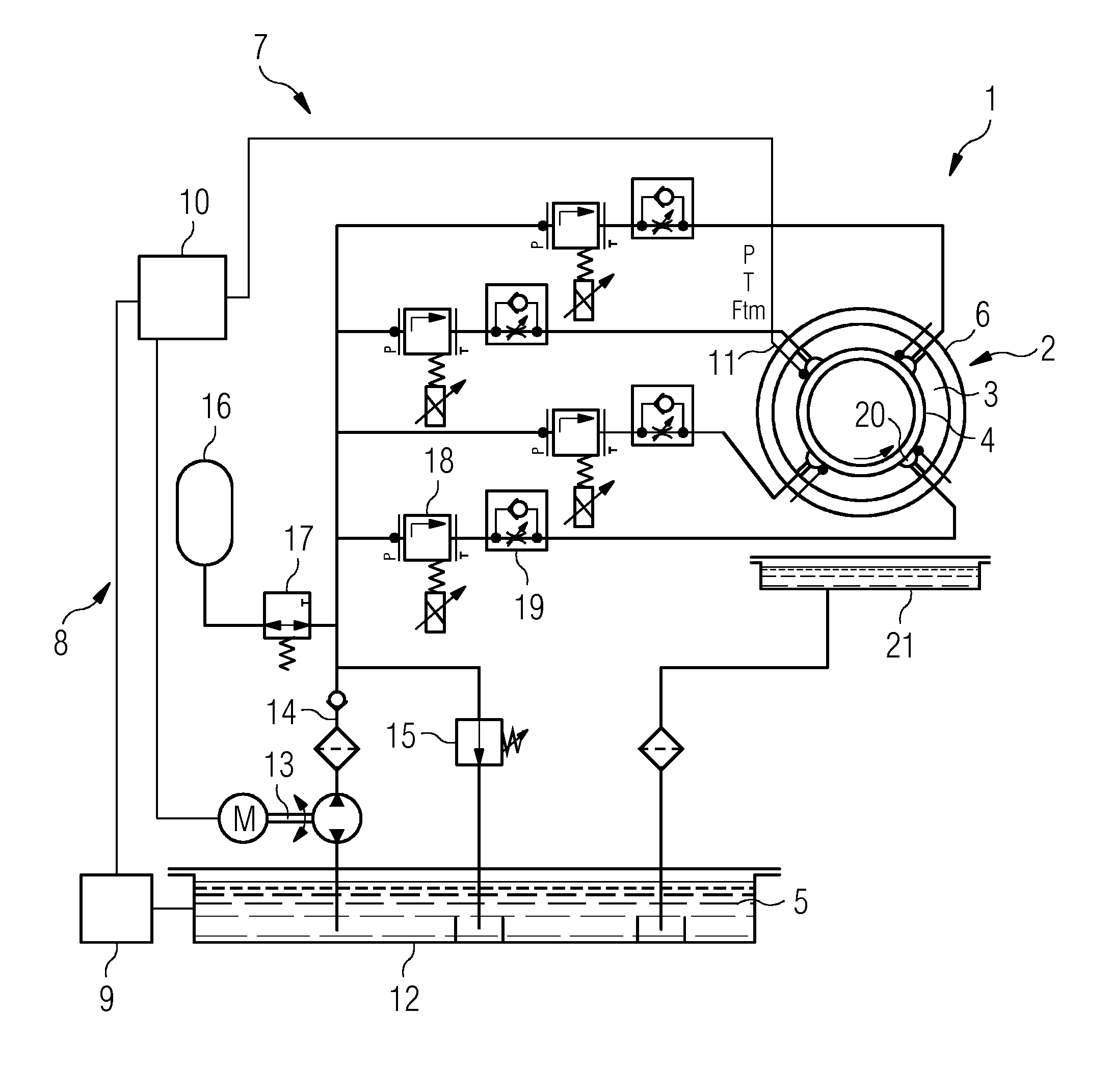
[0031]FIG. 1 shows a wind turbine 1 with a plain / sliding bearing 2. The bearing 2 has an outer ring 3 to which a r...


PUM


Abstract

A wind turbine and method for controlling a wind turbine with a plain/sliding bearing and bearing lubrication means is disclosed. The method comprising the steps of
    • Operating the bearing as a hydrodynamic bearing in normal operation; and
    • Operating the bearing as a hydrostatic bearing when the friction of the bearing reaches a threshold.

Description

CROSS-REFERENCE TO RELATED APPLICATIONS[0001]This application claims priority to PCT Application No. PCT / EP2012 / 073355, having a filing date of Nov. 22, 2012, based off of EP Application No. 12154935.6 having a filing date of Feb. 10, 2012, the entire contents of which are hereby incorporated by reference.FIELD OF TECHNOLOGY[0002]The following relates in general to a wind turbine with a plain / sliding bearing. In particular, the present invention is directed to control the bearing of the wind turbine.BACKGROUND[0003]Future generations of multi MW size direct drive (DD) wind turbines may start to use plain / sliding bearings due to the fact that the current rolling element bearing systems cannot provide adequate lifetime and robustness. One disadvantage with plain / sliding bearings is the operational envelope before full hydrodynamic [HD] film is reached and the bearing surfaces are fully separated by an oil film. In the region of operation before full film separation there will be parti...

Claims


Application Information

Patent Timeline
Patent Type & Authority Applications(United States)
IPC IPC(8): F03D11/00F16C17/12
CPCF16C17/12F03D11/0008F16C33/105F16C2300/14F05B2240/53F16C2360/31F03D80/70F16C17/02F16C17/24F16C32/0648Y02E10/72
Inventor PEDERSEN, BOTHOMSEN, KIM
Owner SIEMENS AG
Why Eureka
Try Eureka