System and method of moving a wind turbine rotor blade

a technology handling system, which is applied in the direction of transportation and packaging, machines/engines, conveying, etc., can solve the problems of complex handling difficulty or impossible deflection of wind turbine rotor blade during handling, etc., and achieve the effect of fewer damage to the wind turbine rotor blad

Active Publication Date: 2014-12-04
SIEMENS GAMESA RENEWABLE ENERGY AS
View PDF10 Cites 27 Cited by
  • Summary
  • Abstract
  • Description
  • Claims
  • Application Information

AI Technical Summary

Benefits of technology

[0006]Thus, there exists a need to provide an improved system for handling a wind turbine rotor blade with fewer damages to the wind turbine rotor blade caused by the handling compared to the state of the art.
[0015]Embodiments of the wind turbine rotor blade handling system as described above may be flexible and can adapt to various rotor blade positions. This can result in smaller loads on the rotor blade. As a consequence, a risk of damages to the rotor blade is reduced.
[0019]The pivot mechanism of the rotor blade handling system can be advantageous when moving or transporting the rotor blade. Due to the pivot mechanism loads and forces, which are exerted on the rotor blade during transportation or moving, may be reduced compared to a fixed attachment of the rotor blade to the rotor blade handling system.
[0022]In an exemplary embodiment, the wind turbine rotor blade handling system comprises a tip part frame and a tip part securing means for securing the tip portion to the tip part frame. The tip part securing means may comprise a clamping yaw, a mounting bracket and / or a strap. A requirement for the tip part securing means is, on the one hand, that the rotor blade is secured safely and in a fixed manner. On the other hand, the rotor blade, e.g. a surface of the rotor blade and / or a structural element of the rotor blade, is not damaged by the tip part securing means. The tip part frame may comprise iron. Embodiments of the tip part frame may be mechanically rigid and stable.
[0023]In an exemplary embodiment, the wind turbine rotor blade handling system comprises a height adjustment means by which the wind turbine rotor blade can be raised and / or lowered relative to a plane where the wind turbine rotor blade handling system is set up. A handling system which is height adjustable can be advantageous. When a rotor blade is transported, it may first be secured to the tip part frame in a low position. When securing is finished, it is, for instance, raised and subsequently the rotor blade is moved by means of the rotor blade handling system.

Problems solved by technology

A current wind turbine rotor blade typically exhibits a size, i.e. a maximum extension, of at least 50 m and can reach a size of up to 100 m. Thus, handling of such a wind turbine rotor blade is challenging.
A disadvantage of current rotor blade handling systems is that the tip portion is rigidly fixed in the tip part and thus deflection of the wind turbine rotor blade during handling, e.g. during rotation, is difficult or impossible.
This causes a problem because of high loads and high forces which are exerted on the rotor blade during rotation.
As a consequence, handling of a wind turbine rotor blade is complicated and damages to the wind turbine rotor blade occur frequently.
However, due to an optimal profile of the rotor blade, the rotor blade is not fully symmetrical.
This can result in smaller loads on the rotor blade.

Method used


Image

  • System and method of moving a wind turbine rotor blade
  • System and method of moving a wind turbine rotor blade
  • System and method of moving a wind turbine rotor blade

Examples


Embodiment Construction

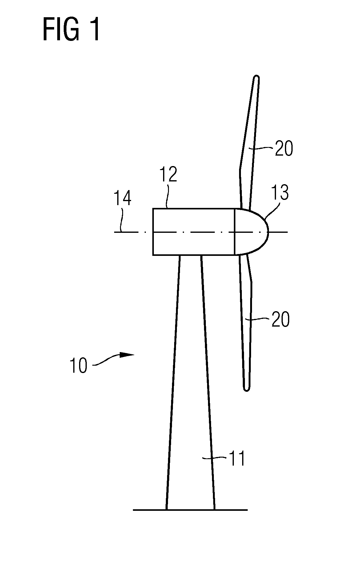
[0051]Referring to FIG. 1, a wind turbine 10 with a tower 11 and a nacelle 12 is shown. The nacelle 12 is connected with a hub 13. Two wind turbine rotor blades 20 are mounted to the hub 13. The hub 13, and thus also the wind turbine rotor blade 20, can be rotated about a rotor axis of rotation 14. The wind turbine 10 is a direct drive wind turbine.

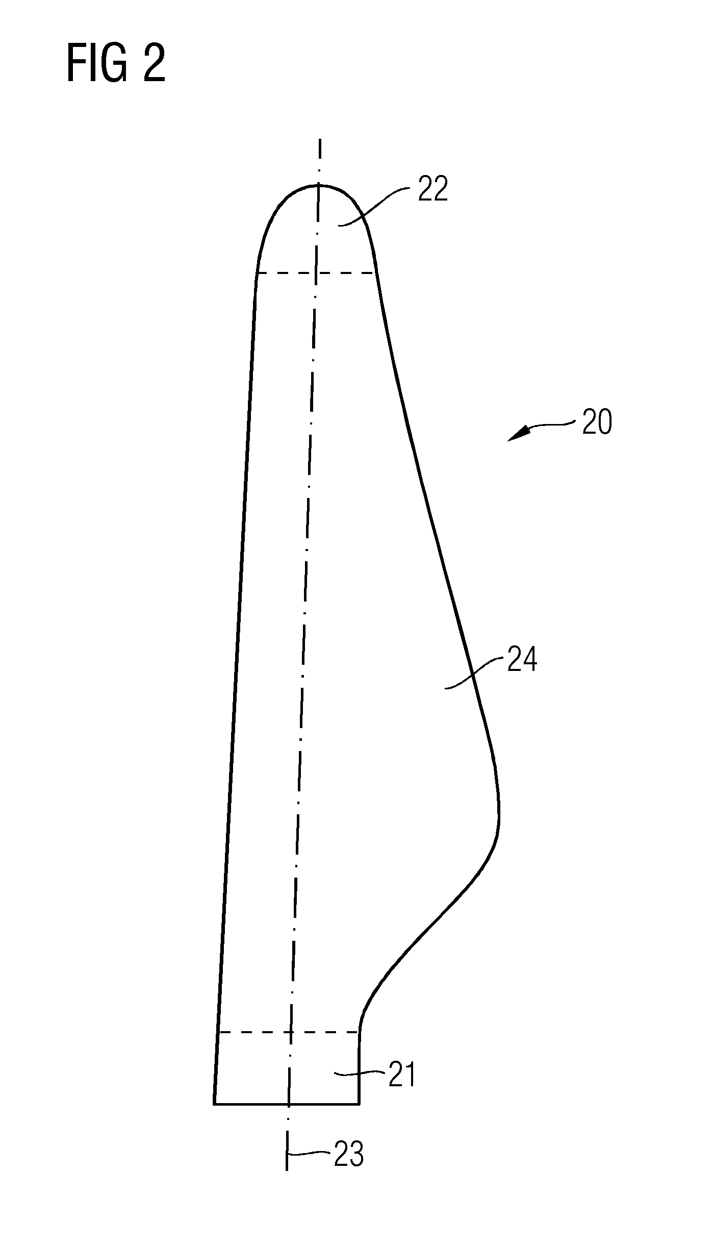
[0052]Referring to FIG. 2, a wind turbine rotor blade 20 is shown. The wind turbine rotor blade 20 is divided in a root portion 21, a tip portion 22 and a main body portion 24. The root portion 21 comprises a shape of a circular cylinder. The root portion 21 comprises a portion of 5% relative to the maximum length of the whole wind turbine rotor blade 20. The tip portion 22 comprises a portion of 30% relative to the wind turbine rotor blade 20.

[0053]Furthermore, the wind turbine rotor blade 20 comprises a virtual axis extending from the root portion 21 to the tip portion 22. This virtual axis is referred to as a rotor blade longitudinal r...


PUM


Abstract

A wind turbine rotor blade handling system for moving a wind turbine rotor blade is provided. The wind turbine rotor blade comprises a root portion, a tip portion and a rotor blade longitudinal rotational axis extending from the root portion to the tip portion. Furthermore, the wind turbine rotor blade handling system comprises a rotary device to rotate the wind turbine rotor blade about the rotor blade longitudinal rotational axis. The rotary device is arranged and prepared for being fastened to the tip portion. Additionally, a method of moving the wind turbine rotor blade by means of the wind turbine rotor blade handling system is also provided.

Description

CROSS-REFERENCE TO RELATED APPLICATIONS[0001]This application claims priority to EP 13169955.5, having a filing date of May 31, 2013, the entire contents of which are hereby incorporated by reference.FIELD OF TECHNOLOGY[0002]The following relates to a wind turbine rotor blade handling system for moving a wind turbine rotor blade, and a method of moving a wind turbine rotor blade by means of such a handling system.BACKGROUND[0003]Rotor blades need to be handled, i.e. moved or transported, during manufacturing of the rotor blade and afterwards. A current wind turbine rotor blade typically exhibits a size, i.e. a maximum extension, of at least 50 m and can reach a size of up to 100 m. Thus, handling of such a wind turbine rotor blade is challenging.[0004]Current rotor blade handling systems comprise at least two parts, a root part and a tip part. To rotate the wind turbine rotor blade, the wind turbine rotor blade is rotated by the root part. In other words, a root portion of the wind ...

Claims


Application Information

Patent Timeline
Patent Type & Authority Applications(United States)
IPC IPC(8): B65G47/82
CPCB65G47/82F05B2260/30Y02E10/72F03D13/40
Inventor SCHMIDT, THOMAS POSBORGVENNEGAARD, SOEREN BAEK
Owner SIEMENS GAMESA RENEWABLE ENERGY AS
Why Eureka
Try Eureka