Radio frequency transmitter, power combiners and wireless communication unit therefor

a radio frequency transmitter and combiner technology, applied in the direction of fixed transformers, mutual inductances, antennas, etc., can solve the problems of high manufacturing costs of iii-v technologies, inability to provide a complete system-on-chip solution, and difficult to achieve these specifications using cmos technology, etc., to achieve the effect of facilitating the reduction of inductive coupling

Active Publication Date: 2014-12-04
MEDIATEK INC
View PDF1 Cites 7 Cited by
  • Summary
  • Abstract
  • Description
  • Claims
  • Application Information

AI Technical Summary

Benefits of technology

[0032]According to an optional feature of the invention, the first pair of cross-coupled bond wires may form a planar figure-8 shaped primary winding and the second pair of cross coupled bond wires may form a planar figure-8 shaped secondary winding, and a second planar figure-8 shaped primary winding, thereby forming a figure-88 shaped primary winding; and a second planar figure-8 shaped secondary winding thereby forming a figure-88 shaped secondary winding. The figure-88 shaped primary winding may be substantially overlaid with the figure-88 shaped secondary winding. In one example, the overlaid location of the figure-88 shaped primary winding and figure-88 shaped secondary winding may be operable to facilitate reduction of inductive coupling.

Problems solved by technology

It is currently very difficult to achieve these specifications using CMOS technology.
However, III-V technologies have high manufacturing costs, as well as being unable to provide a complete system-on-chip (SoC) solution.
Due to the closeness of many of the inductive components within the integrated RF PA system 100, there are a number of potentially problematic effects.
These can be caused by an imbalanced impedance transformation and poor common-mode harmonic suppression within the integrated power combiner devices 150, 170.
However, this is not always a viable option for devices when trying to reduce the overall size of the integrated system 100.
This, again, can be caused by an imbalanced impedance transformation and poor common-mode harmonic suppression.
A potential problem with this structure is that the primary windings 260, 270, 280, 290 will still couple to each other, which would result in an imbalanced impedance transformation and poor common-mode harmonic suppression at each differential port.
In some severe cases, an imbalanced impedance transformation may affect the output power and efficiency of this structure.
It is known that mutual coupling can be a serious problem for certain devices, for example radio frequency transceivers, as the effect of mutual coupling can change antenna array radiation patterns and alter matching characteristics of antenna elements.

Method used


Image

  • Radio frequency transmitter, power combiners and wireless communication unit therefor
  • Radio frequency transmitter, power combiners and wireless communication unit therefor
  • Radio frequency transmitter, power combiners and wireless communication unit therefor

Examples


Embodiment Construction

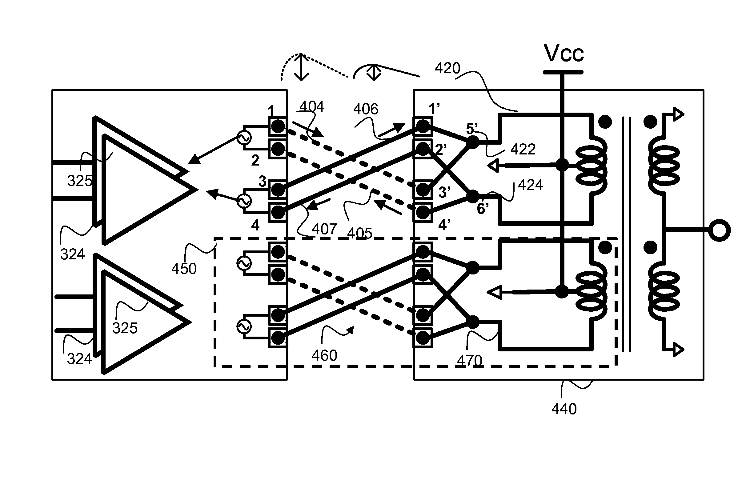
[0045]Examples of the invention will be described in terms of a radio frequency (RF) transmitter, comprising: a plurality of power amplifier stages comprising a plurality of paired output terminals (1-2; 3-4), where a pair of output terminals is coupled to a respective amplifier stage. A power combining arrangement comprises: a plurality of first paired input terminals (1′-3′; 2′-4′), a plurality of second input terminals (5′, 6′), such that each input of the first paired input terminals is coupled to the same second input terminal (1′ and 3′ coupled to 5′; 2′ and 4′ coupled to 6′); and a power transfer circuit operably coupling the second input terminals (5′, 6′). A first pair of cross coupled bond wires operably couples a pair of amplifier stage output terminals (e.g. (1,2)) with a different second input terminal (5′, 6′) via terminals of different pairs of the plurality of first paired input terminals (e.g. (1-3′-5′) and (2-4′-6′)) of the power combining arrangement; and a second...


PUM


Abstract

A radio frequency transmitter includes: power amplifier stages having paired output terminals, where a pair of output terminals is coupled to a respective amplifier stage. A power combining arrangement includes: first paired input terminals, second input terminals, such that each input of the first paired input terminals is coupled to the same second input terminal; and a power transfer circuit coupling the second input terminals. A first pair of cross coupled bond wires couples a pair of amplifier stage output terminals with a different second input terminal via terminals of different pairs of the first paired input terminals; and a second pair of cross coupled bond wires overlays the first pair of cross coupled bond wires and couples a further pair of amplifier stage output terminals with a different second input terminal via terminals of different pairs of the first paired input terminals.

Description

CROSS REFERENCE TO RELATED APPLICATIONS[0001]This application claims the benefit of U.S. provisional application No. 61 / 828,850, filed on May 30, 2013 and incorporated herein by reference.BACKGROUND[0002]1. Field of the Invention[0003]The field of this invention relates to radio frequency transmitters having power combiners. The invention is applicable to, but not limited to, efficient power combining techniques.[0004]2. Background of the Invention[0005]In the field of complementary metal-oxide-semiconductor (CMOS) power amplifiers, there is a constant demand by consumers for wireless systems that are low cost, efficient and reliable. High level integration has been shown in practice to be an effective way to reduce cost and achieve compactness for high volume applications. Currently, almost all power amplifiers are manufactured with III-V compound semiconductors, as this type of device has high output power and high power efficiency, which are desired attributes for many power ampl...

Claims


Application Information

Patent Timeline
Patent Type & Authority Applications(United States)
IPC IPC(8): H04B1/04
CPCH04B1/0458H01F19/04H03H7/48
Inventor TSAI, MING-DA
Owner MEDIATEK INC
Why Eureka
Try Eureka