Single cordless control for window covering

a single-cordless control and window covering technology, applied in door/window protective devices, building components, construction, etc., can solve the problems of choking, children are also known to accidentally become caught in the lower loop, and the horizontal tape section tilts and consequently tilts, so as to reduce the potential for tangles

Inactive Publication Date: 2014-12-11
LEE HAN SEN
View PDF22 Cites 8 Cited by
  • Summary
  • Abstract
  • Description
  • Claims
  • Application Information

AI Technical Summary

Benefits of technology

The patent describes a window covering slat set that can be adjusted using a single mechanical input. This eliminates the need for control cords and allows for easy adjustment of the slat angle and position. The slats can be raised or lowered by turning a central turn axle, and the angle of tilt can be adjusted by turning the axle in the opposite direction. The slat tilt fitting is designed to prevent tangles and provide a controlled space for the slats to operate without binding. The technical effects of this invention include simplified and convenient adjustment of window covering slats, improved slat angle adjustment, and reduced risk of damage to the slats.

Problems solved by technology

Movement of the front vertical ladder tape with respect to the rear vertical ladder tape caused a tilting of the horizontal tape section and consequent tilting of the supported louver or slat resting on the horizontal tape section.
Children were also known to accidentally become caught in the lower loop.
In some cases choking can occur.
This arrangement works less well with vertically tall window covering sets because the raising of the slat set puts even more loose cord at or near the ground.
Further, where the window covering set was particularly vertically high, the user might find the uppermost starting position of the coordinated cords to be inaccessible.
Window covering sets which are “routless” generally still typically use a lift cord set which can come into contact near the floor and create a danger for children and pets.
However there has been no effective substitute for the operation of the lift cord sets.
Even in conventional manually operated window covering sets, the concern over safety is so high that even those structures with hanging slat lift cords often have stops mounted on the manually operable lift cords near the points of entry into the head rail and that will prevent children and pets from “fishing out” any appreciable extra length of lift slat cord from in between any two adjacent slats, as such pick might form a potentially dangerous loop.

Method used


Image

  • Single cordless control for window covering
  • Single cordless control for window covering
  • Single cordless control for window covering

Examples


Embodiment Construction

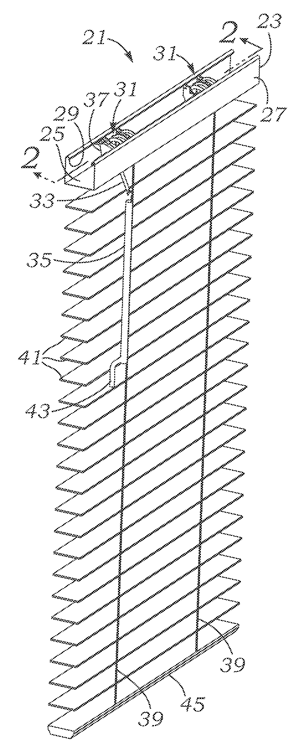
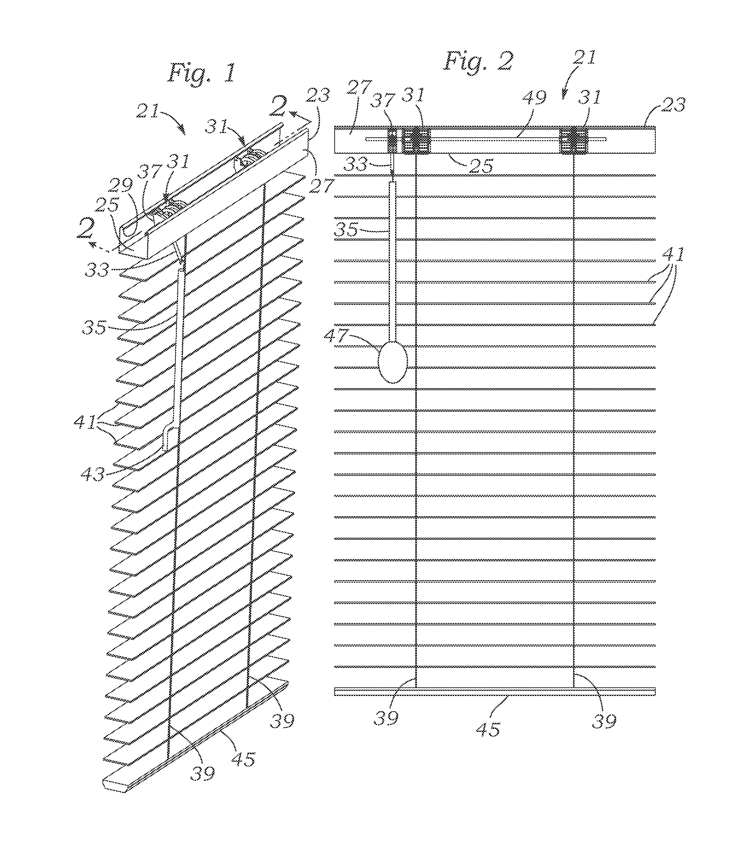
[0052]The description and operation of the environment, apparatus and method of the invention will be best described with reference to FIG. 1 which illustrates a perspective view of a window covering window blind set 21 having a head rail 23 having a transverse overall “U” shape and securing a pair of combination slat angle adjustment and window covering opening lift sets 31 which are only partially seen over the top of the head rail 23. Head rail 23 has a base wall 25 and a pair of side walls 27 which have upper portions that terminate in a downwardly directed edge 29. The window covering window blind set 21 is seen as having a single control input fitting 33 which is attached to a manual wand 35. The other end of single control input fitting 33 is attached to a reduction gear 37 which is see just to the left of the leftmost combination slat angle adjustment and window covering opening lift sets 31. Reduction gear may have a turning reduction ratio between 1:2 and 1:8 and may prefe...


PUM


Abstract

A single control input is realized with the use of a combination slat angle adjustment and window covering opening lift set structure which may be operated by a single wand. A three segment relative control logic is realized which includes movement within in the middle segment that controls the angle of the slats, and movement to and beyond the position where the slats are maximally angled in one direction results in at least one of opening (raising) or closing (lowering) of the slat set by “winding up” a lift cord set which may operate on the interior or exterior of the slat set.

Description

FIELD OF THE INVENTION[0001]The present invention relates to a mechanism and process for providing actuation of a single control in order to raise and lower window covering blind sets, as well as to control the angle of tilt of window covering blind sets. The structure and method enables elimination of user actuatable dangling cords and further pe nits simplification and mass automation of control and operation of a window covering blinds set to enhance safety.BACKGROUND OF THE INVENTION[0002]Conventional window coverings which use a series of horizontally disposed, vertically arranged slats are available in a variety of styles. The typical structure for supporting the slats vertically spaced from each other includes an end ladder arrangement having a series of cross connectors upon which the slats rest. In the 1950's the ladder arrangement included a wide tape and the cross connectors included a series of generally horizontal tape sections joining the a front and rear vertical ladd...

Claims


Application Information

Patent Timeline
IPC IPC(8): A47H5/032
CPCA47H5/032E06B9/303E06B9/322E06B2009/3222E06B9/384E06B9/30
Inventor LEE, HAN-SEN
Owner LEE HAN SEN
Why Eureka
Try Eureka