Mount apparatus

a technology of mounting apparatus and actuator, which is applied in the direction of electric propulsion mounting, shock absorption mounting, jet propulsion mounting, etc., can solve the problems of unfavorable surface area ratio, and achieve the effect of reducing actuator stroke, increasing surface area, and amplifying volume chang

Active Publication Date: 2014-12-11
BEIJING WEST IND CO LTD
View PDF11 Cites 2 Cited by
  • Summary
  • Abstract
  • Description
  • Claims
  • Application Information

AI Technical Summary

Benefits of technology

[0007]The invention provides for such a mount apparatus for supporting a vibration source on a base. The hydraulic mount comprises a housing extending about and along a first axis and defining a housing chamber, a flexible body made of an elastic material at least partially disposed in the housing chamber to define a pumping chamber configured to be filled with a fluid within the housing chamber, the flexible body being interconnected with the housing for deforming elastically in response to movement of the vibration source relative to the housing caused by an external excitation, a moving member at least partially disposed in the pumping chamber for moving within the pumping chamber, and an actuator operatively coupled to the moving member for moving the moving member to create a volume change in the pumping chamber to maintain the volume of said pumping chamber to prevent a pressure increase in the pumping chamber during the deformation of the flexible body in response to the external excitation to effectively cancel the external excitation. The moving member includes an axially extending moveable wall of a flexible material and defines a moving member chamber for flexing radially outwardly and inwardly relative to the first axis to amplify the volume change in the pumping chamber.
[0008]Thus several advantages of one or more aspects of the invention are that the moveable wall provides for increased surface area of the moving member, therefore a smaller actuator stroke is required to effectively cancel the external excitation, while utilizing the limited radial space of the housing chamber. The increased surface of the moving member is particularly advantageous when used with actuators like piezostack actuators which have relatively short actuator strokes. Piezostack actuators are attractive for this application due to their very high response speed and frequency bandwidth

Problems solved by technology

A known problem with such mount apparatuses is that the commonly piston-shaped moving members have an unfavorable surface area ratio compared to the surface area of the flexible body, thus requiring a relatively large stroke of the actuator relative to the displacement of the flexible body in order to effectively cancel the external excitation.

Method used


Image

  • Mount apparatus
  • Mount apparatus

Examples


Embodiment Construction

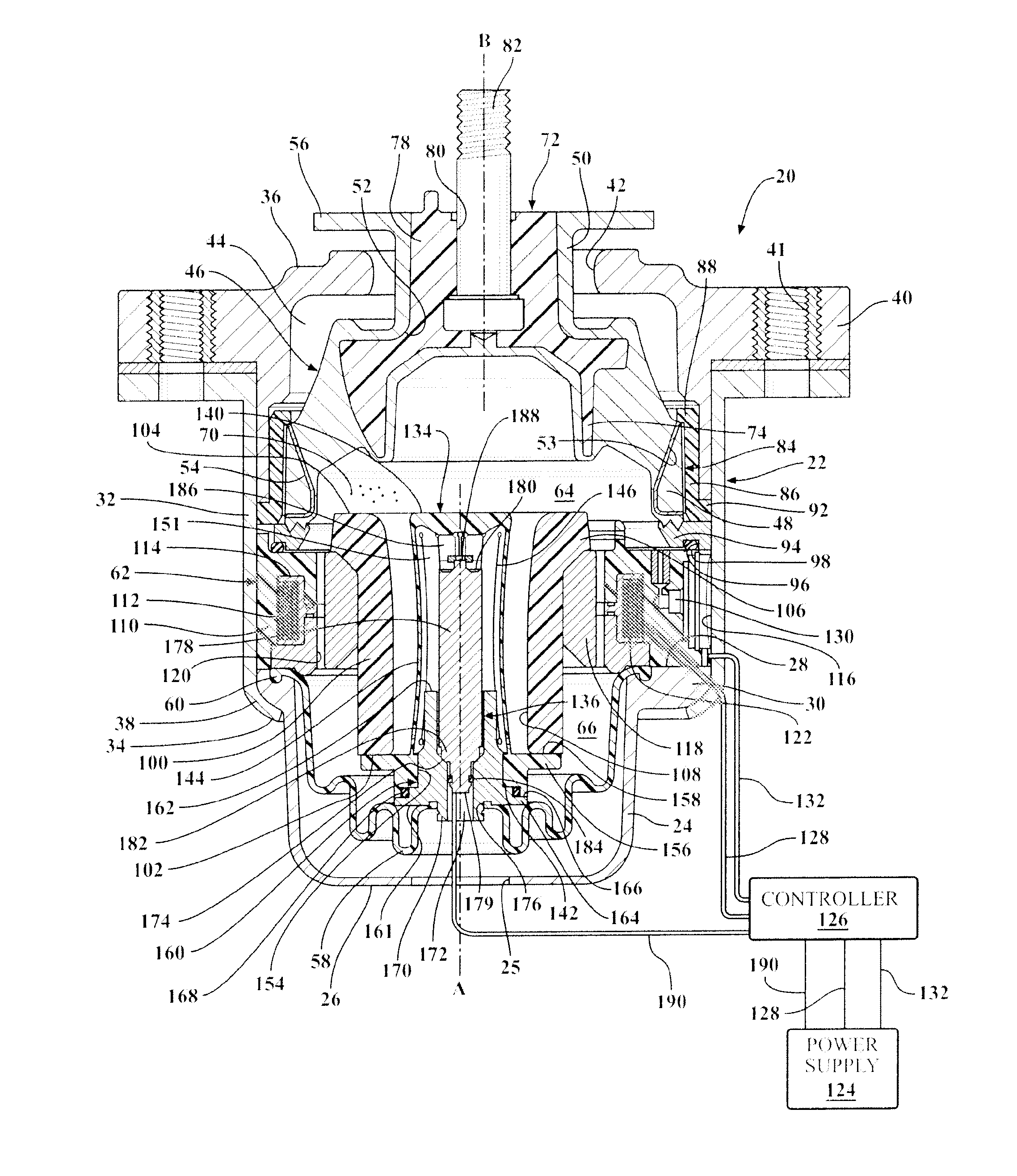
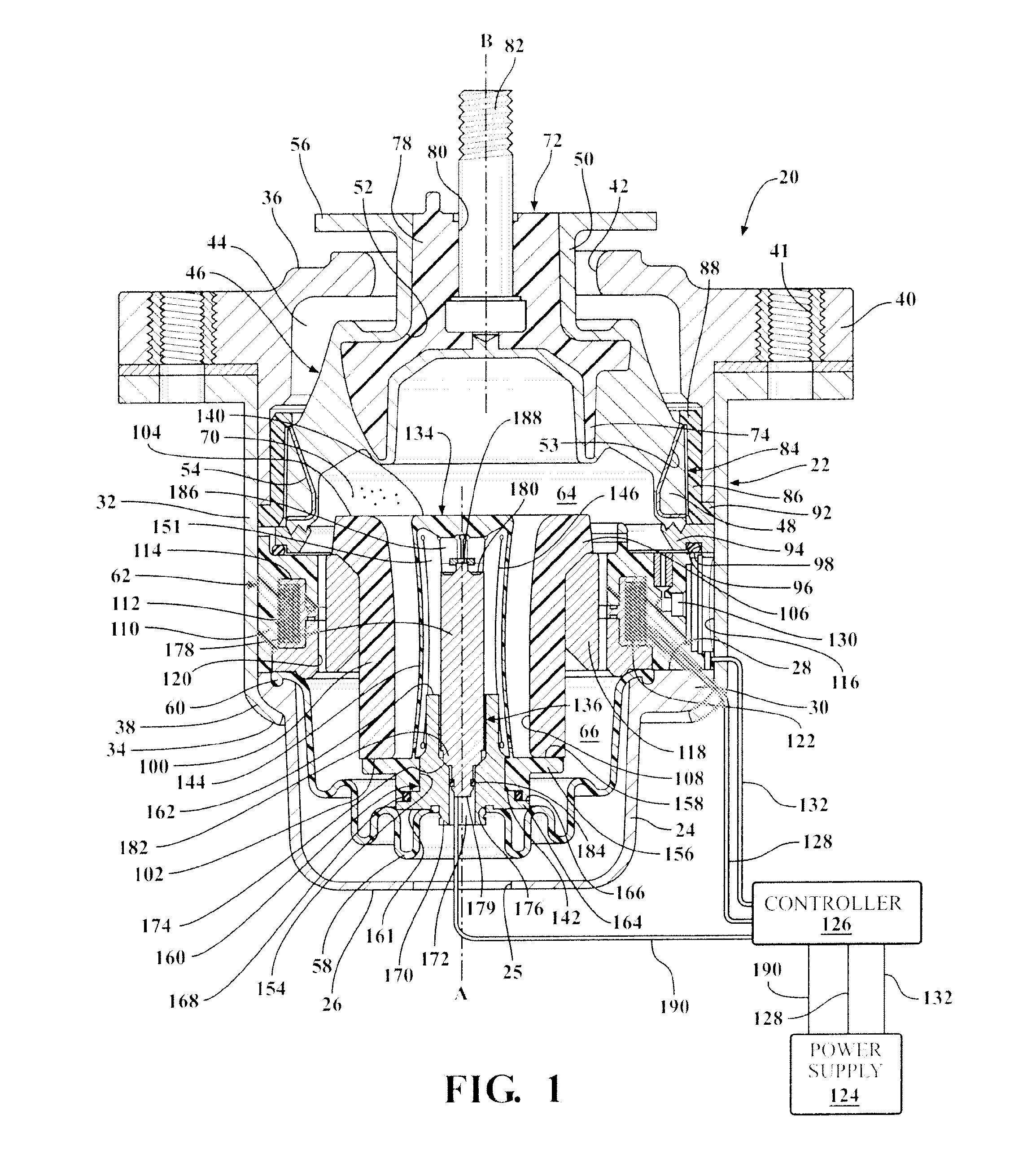
[0011]Referring to FIG. 1, a hydraulic mount apparatus 20 is generally shown for supporting a vibration source on a base. In the enabling embodiment, the hydraulic mount apparatus 20 is used for supporting a component of an automobile (e.g. an engine) on the frame of an automotive vehicle. However, it should be appreciated that the mount apparatus could be used for supporting various other vibration sources on a base.

[0012]The hydraulic mount apparatus includes a housing 22 that includes a generally bowl-shaped lower housing portion 24 that extends annularly about and along a first axis A from a closed lower housing portion lower end 26 to an open lower housing portion upper end 28. The lower housing portion 24 defines a lower housing portion lip 30 that extends radially outwardly from the lower housing portion 24 adjacent the lower housing portion upper end 28. The lower housing portion lower end 26 further defines a lower housing portion bore 25 that extends through the lower hous...


PUM


Abstract

A mount apparatus (20) for supporting a vibration source on a base is provided. The mount apparatus (20) includes a moving member (134) that is partially disposed in a pumping chamber (64) for moving within the pumping chamber (64) along a first axis (A) to create a volume change in the pumping chamber (64) to maintain the volume of the pumping chamber (64) to prevent a pressure increase in the pumping chamber (64) during the deformation of a flexible body (46) in response to an external excitation to effectively cancel the external excitation. The moving member (134) includes a moveable wall (144) of a flexible material, having a generally hour glass-shape in steady state, and extending between moving member upper and lower ends (140, 142). The moveable wall (144) flexes radially outwardly and inwardly relative to the first axis (A) in response to relative axial movement between the moving member upper and lower ends (140, 142), to amplify the volume change in the pumping chamber (64).

Description

BACKGROUND OF THE INVENTION[0001]1. Field of the Invention[0002]The present invention relates to a mount apparatus for supporting a vibration source on a base, more particularly, to an active hydraulic mount apparatus.[0003]2. Description of the Prior Art[0004]Conventional mounts exist for supporting and providing vibration isolation of vibration sources. One well-known application of these mounts is for supporting components of automotive vehicles. These mounts typically operate to provide engine vibration isolation while also to control the motion of the engine and connected powertrain components with respect to the vehicle frame or body structure. In many applications of engine and powertrain mounts, it is desirable to vary damping characteristics of the mount to provide selective isolation of vibrations at certain frequencies.[0005]One such hydraulic mount apparatus is disclosed in U.S. Pat. No. 5,439,204 to Yamazo et al. The mount includes a housing that extends about and along...

Claims


Application Information

Patent Timeline
Patent Type & Authority Applications(United States)
IPC IPC(8): B60K5/12F16F13/26
CPCF16F13/26B60K5/12F16F13/264
Inventor FARJOUD, ALIREZABARTA, DAVID JOHNFOURMAN, BRENT WADEMICHAEL, CHADSCHUMANN, ERIC LOUIS
Owner BEIJING WEST IND CO LTD
Why Eureka
Try Eureka