
Copper electroplating apparatus

a technology of copper electroplating and copper plate, which is applied in the direction of electrolysis process, semiconductor devices, electrolysis components, etc., can solve the problems of substrate damage, difficult to produce firm black film in a manner, and inability to permeate non-ionic organic additives, etc., and achieves uniform thickness and simple construction

Inactive Publication Date: 2014-12-11
EBARA CORP
View PDF6 Cites 11 Cited by
  • Summary
  • Abstract
  • Description
  • Claims
  • Application Information

AI Technical Summary

Benefits of technology

The technical effect of this patent is to provide a copper electroplating apparatus that can stably retain a black film on the surface of a soluble anode of phosphorus-containing copper, without peeling off excessively. Additionally, it aims to prevent the black film from being attached to a substrate more reliably with a relatively simple construction, in case it peels off the soluble anode.

Problems solved by technology

The black film suspended in the plating solution, if it is attached to a substrate, may cause a defect in the substrate.
A plating apparatus has been proposed which comprises an anode chamber and a cathode chamber that are separated by a porous transmissive bather of a multi-layer structure which allows permeation of metal ions therethrough but does not allow permeation of non-ionic organic additives (see U.S. Pat. No. 6,527,920).
It is generally difficult to produce a firm black film in a manner as not to peel off the underlying surface of the phosphorus-containing copper anode.
Moreover, use of a fairly complicated construction is generally required in order to prevent a black film, which has peeled off a phosphorus-containing copper anode, from adhering to a substrate.
In particular, a very complicated structure will be needed to completely prevent a black film from adhering to a substrate.

Method used


Image

  • Copper electroplating apparatus
  • Copper electroplating apparatus
  • Copper electroplating apparatus

Examples


Embodiment Construction

[0036]Embodiments of the present invention will now be described with reference to the drawings. The same reference numerals are used in the following figures and description to refer to the same or like members, components, etc., and a duplicate description thereof will be omitted.

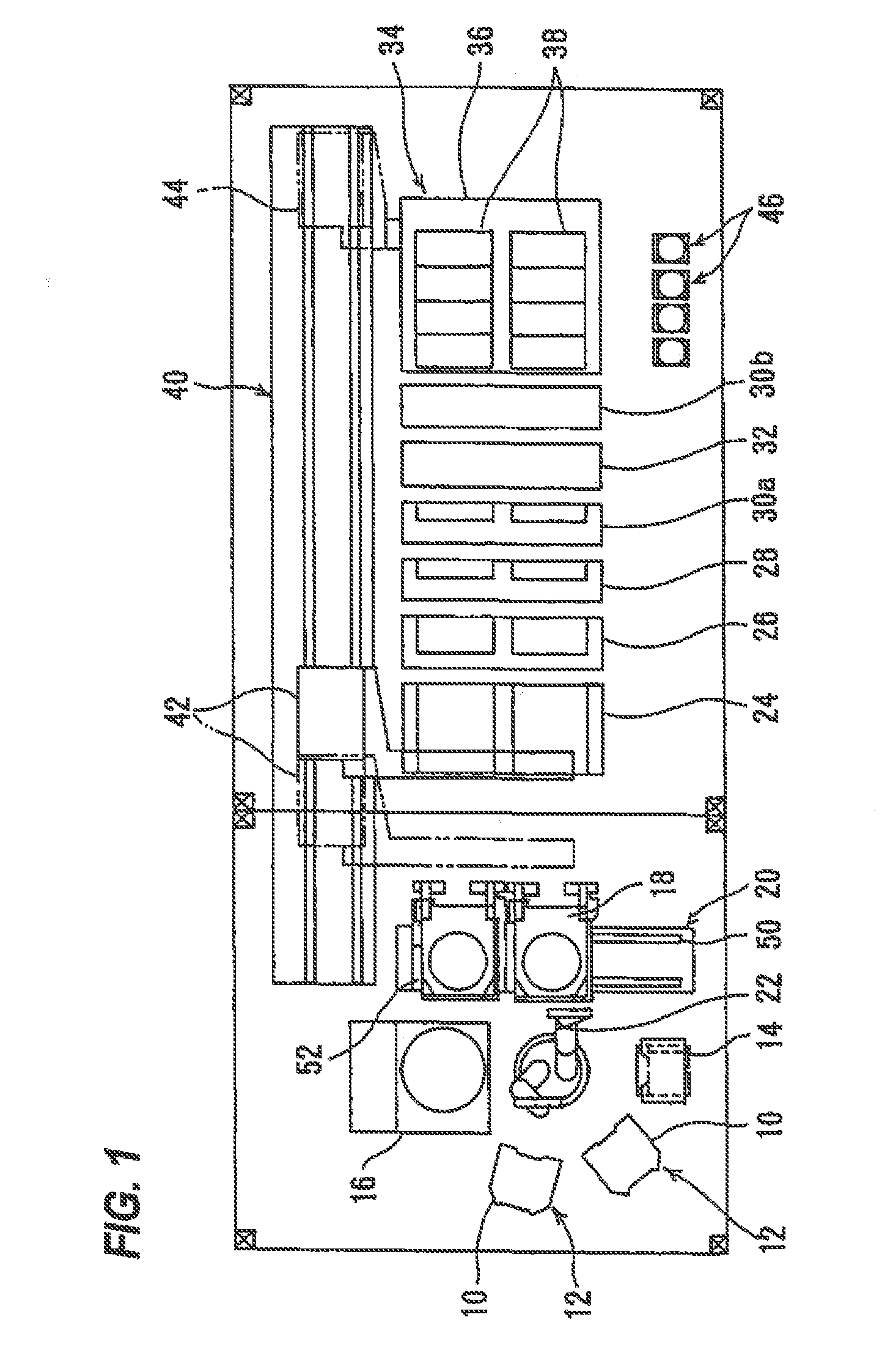
[0037]FIG. 1 shows an overall layout plan of a copper electroplating apparatus according to an embodiment. As shown in FIG. 1, the copper electroplating apparatus includes two cassette tables 12 on which substrate cassettes 10, each storing therein substrates, such as semiconductor wafers, are placed, an aligner 14 for aligning an orientation flat or a notch of a substrate in a predetermined direction, and a spin rinse drier 16 for drying a plated substrate by rotating it at a high speed. Near the spin rinse drier 16 is provided a substrate loading unit 20 for placing a substrate holder 18 thereon and loading the substrate into the substrate holder 18 and removing the substrate from the substrate holder 1...


PUM

PropertyMeasurementUnit
grain sizeaaaaaaaaaa

Abstract

A copper electroplating apparatus is disclosed. The copper electroplating apparatus includes: a plating bath configured to hold a plating solution therein; a soluble anode of phosphorus-containing copper; a substrate holder configured to hold a substrate; an anode bag that surrounds the anode, the anode bag being formed of mesh; a regulation plate configured to regulate an electric field, the regulation plate having an opening and being disposed between the anode and the substrate held by the substrate holder; and a diaphragm disposed so as to dose the opening of the regulation plate, the diaphragm being configured to allow permeation of metal ions therethrough and not allow permeation of additives contained in the plating solution.

Description

CROSS REFERENCE TO RELATED APPLICATION[0001]This application claims priority to Japanese Patent Application No. 2013-119744 filed Jun. 6, 2013, the entire contents of which are hereby incorporated by reference.BACKGROUND[0002]A soluble anode made of phosphorus-containing copper (hereinafter referred to as “phosphorus-containing copper anode”) is widely used in a known type of copper electroplating apparatus which performs copper plating of a substrate surface by immersing a substrate such as a semiconductor wafer, held by a substrate holder, in a plating solution. When using a phosphorus-containing copper anode, it is common practice to perform dummy plating by applying a voltage between a dummy substrate and the phosphorus-containing copper anode to produce a thin film, called a black film, uniformly on the surface of the phosphorus-containing copper anode before applying a voltage between a substrate and the phosphorus-containing copper anode to perform copper plating of the subst...

Claims


Application Information

Patent Timeline
Patent Type & Authority Applications(United States)
IPC IPC(8): C25D17/12C25D7/12
CPCC25D7/123C25D17/12C25D3/38C25D17/001C25D17/002C25D17/008C25D17/10C25D21/10
Inventor KIMURA, MASAAKIYAHAGI, MITSUTOSHITSUJINO, JUNICHIRO
Owner EBARA CORP
Features
  • Generate Ideas
  • Intellectual Property
  • Life Sciences
  • Materials
  • Tech Scout
  • Unparalleled Data Quality
  • Higher Quality Content
  • 60% Fewer Hallucinations
Learn More