
Rubber composition for rubber vibration insulator

a technology of vibration insulation and rubber, which is applied in the direction of shock absorbers, mechanical equipment, transportation and packaging, etc., can solve the problems of high dynamic-to-static modulus ratio, poor damping properties crystallization and hardness of rubber vibration insulation, etc., to achieve superior fundamental properties and damping properties, and improve heat resistance and low-temperature performance.

Active Publication Date: 2014-12-11
BRIDGESTONE CORP
View PDF3 Cites 12 Cited by
  • Summary
  • Abstract
  • Description
  • Claims
  • Application Information

AI Technical Summary

Benefits of technology

The rubber composition in this patent makes a better rubber vibration insulator that can handle heat and low temperatures well. It also has good properties and damping abilities.

Problems solved by technology

However, the high-cis butadiene rubber is liable to crystallize and become hard in a cold environment, and consequently it does not fully exhibit its damping properties when the engine is started at an extremely low temperature.
Although it is possible to avoid crystallization and prevent aggravation of low-temperature properties by using a butadiene rubber with a low content of cis-1,4 bonds and a high content of trans-1,4 bonds (which is referred to as low-cis butadiene rubber hereinafter), the resulting rubber vibration insulator is poor in damping properties and has a high dynamic-to-static modulus ratio.
However, the reduction of sulfur content to such an extent as to achieve the desired heat resistance is liable to aggravate damping properties and low-temperature performance.
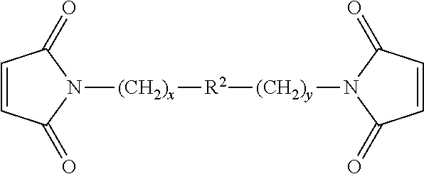
The proposed method has a disadvantage that the bismaleimide compound deteriorates the fundamental properties if it is added in an excess amount.
However, there is a need for improvement because the low-temperature performance does not reach a demand level.
As mentioned above, the rubber vibration insulator has fundamental properties, damping properties, heat resistance, and low-temperature performance which are mutually contradictory, and it has been difficult to improve such properties altogether by compounding in a conventional way.

Method used


Image

  • Rubber composition for rubber vibration insulator
  • Rubber composition for rubber vibration insulator

Examples


examples

[0065]The invention will be described in more detail with reference to the following Examples and Comparative Examples, which are not intended to restrict the scope thereof.

examples 1 , 11

Examples 1, 11, and 12 and Comparative Examples 1, 8, and 9

[0093]These Examples are intended to see how the rubber composition for rubber vibration insulators varies in performance depending on the type of carbon black. Samples of the rubber composition, in Examples 1, 11, and 12 and Comparative Examples 1, 8, and 9, were prepared by kneading from the components shown in Table 3 below. The resulting rubber compositions were vulcanized and tested for hardness (Hd), tensile elongation (Eb), tensile strength (Tb), heat resistance, static spring constant (Ks), dynamic-to-static modulus ratio (Kd / Ks), and low-temperature performance, in the same way as mentioned above. The results of the test are also shown in Table 3.

TABLE 3ComparativeExampleExample11112189FormulationNR80.080.080.0100.0100.0100.0(parts by weight)High-cis-high-vinyl20.020.020.0butadiene rubberCarbon black FT30.030.0Carbon black FEF30.030.0Carbon black HAF30.030.0Stearic acid1.01.01.01.01.01.0Zinc oxide3.03.03.03.03.03.0W...


PUM

PropertyMeasurementUnit
Fractionaaaaaaaaaa
Fractionaaaaaaaaaa
Fractionaaaaaaaaaa

Abstract

A rubber composition gives rise to a rubber vibration insulator superior not only in heat resistance and low-temperature performance but also in fundamental properties and damping properties. The rubber composition for rubber vibration insulator comprising: a rubber component comprising high-cis-high-vinyl butadiene rubber containing 85 to 93% of cis-1,4 bonds and 5 to 13% of vinyl bonds, sulfur, and a bismaleimide compound, wherein the sulfur is included in an amount of up to 1 part by weight, per 100 parts by weight of the rubber component.

Description

CROSS-REFERENCE TO RELATED APPLICATION[0001]This non-provisional application claims priority under 35 U.S.C. §119(a) on Patent Application No. 2013-120537 filed in Japan on Jun. 7, 2013, the entire contents of which are hereby incorporated by reference.TECHNICAL FIELD[0002]The present invention relates to a rubber composition for rubber vibration insulator, which gives rise to a rubber vibration insulator superior not only in heat resistance and low-temperature performance but also in fundamental properties and damping properties.BACKGROUND ART[0003]It has been a common practice to improve the riding comfort of automobiles and other vehicles by attaching a variety of vibration insulators to the source of vibration and noise, thereby reducing vibration and noise entering the compartment. For example, rubber vibration insulators are used as constituents of the torsional damper and engine mount in the case where the engine is the major source of vibration and noise. The resulting effec...

Claims


Application Information

Patent Timeline
IPC IPC(8): F16F1/36B60R13/08
CPCF16F1/3605B60R13/0876B60R13/0838C08L7/00C08L91/06C08K5/3415C08K3/04C08K3/06C08K5/09C08K5/47C08L9/00C08L91/00C08K2003/2296
Inventor NAGATA, TAKESHI
Owner BRIDGESTONE CORP
Learn More