
Air guiding element

a technology of air guiding and guiding apron, which is applied in the direction of roofs, transportation and packaging, vehicle arrangements, etc., can solve the problems of unavoidable impact of the trailer on the air guiding apron, high fuel consumption, and collision of the front edge of the trailer vehicle on the inside of the curve with the tractive vehicl

Active Publication Date: 2014-12-11
JOST WERKE
View PDF7 Cites 7 Cited by
  • Summary
  • Abstract
  • Description
  • Claims
  • Application Information

AI Technical Summary

Benefits of technology

The invention aims to provide an air guide that requires minimal maintenance and is safe to operate. This element can be installed separately from the vehicle's air supply to enhance the air flow between a tractor and a trailer for better efficiency.

Problems solved by technology

Between the tractive vehicle and the trailer vehicle in the coupled state there is a gap, which produces considerable turbulence of the passing air during travel and thus causes a relatively high fuel consumption.
However, a minimum gap width is needed, since a relative movement between tractive vehicle and trailer vehicle occurs especially when negotiating curves and without it there is the danger of the front edge of the trailer vehicle on the inside of the curve colliding with the tractive vehicle in the case of a sharp curve.
The major drawback to this known air guiding apron is its adjustment before driving away and the resulting unavoidable impact of the trailer against the air guiding apron.
This always causes damage to the air guiding apron or the trailer.
It has proven to be a drawback that the tractive vehicle needs to be outfitted with a substantial compressor power in order to fill the volume of the air bag, several cubic meters in size, in addition to the braking system.
This problem is further aggravated when the air bag loses tightness due to damage and therefore the compressor is no longer able to fill the pressure accumulator of the brake system.
In some cases, this may lead to loss of the brake system, so that the articulated vehicle is disabled from driving.

Method used


Image

  • Air guiding element
  • Air guiding element
  • Air guiding element

Examples


Embodiment Construction

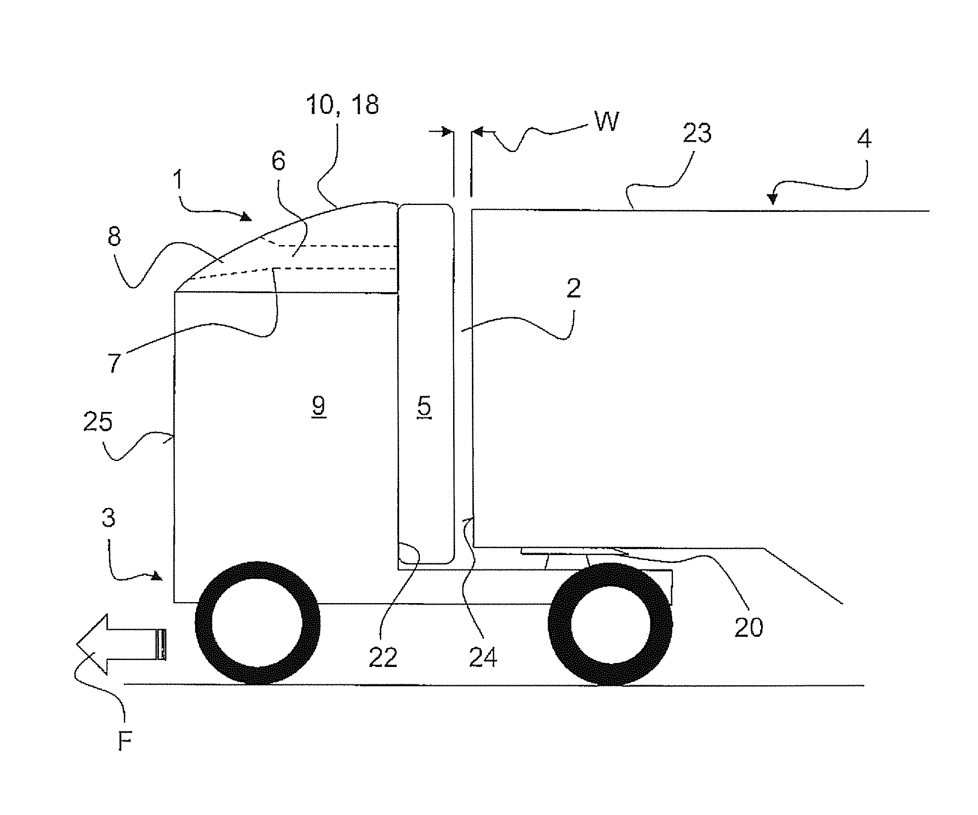
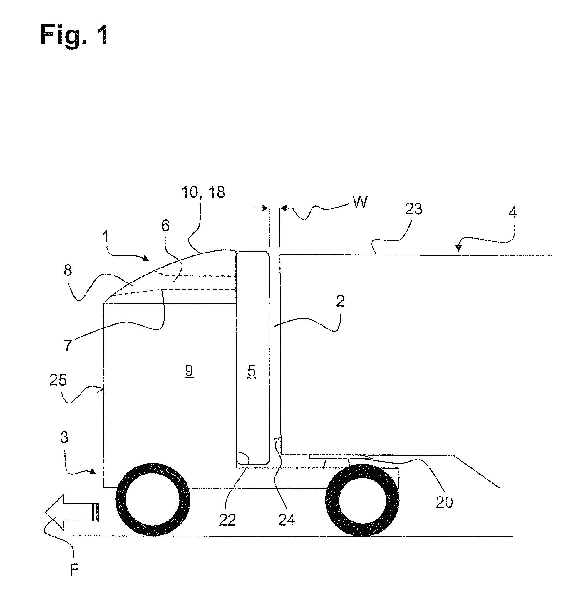
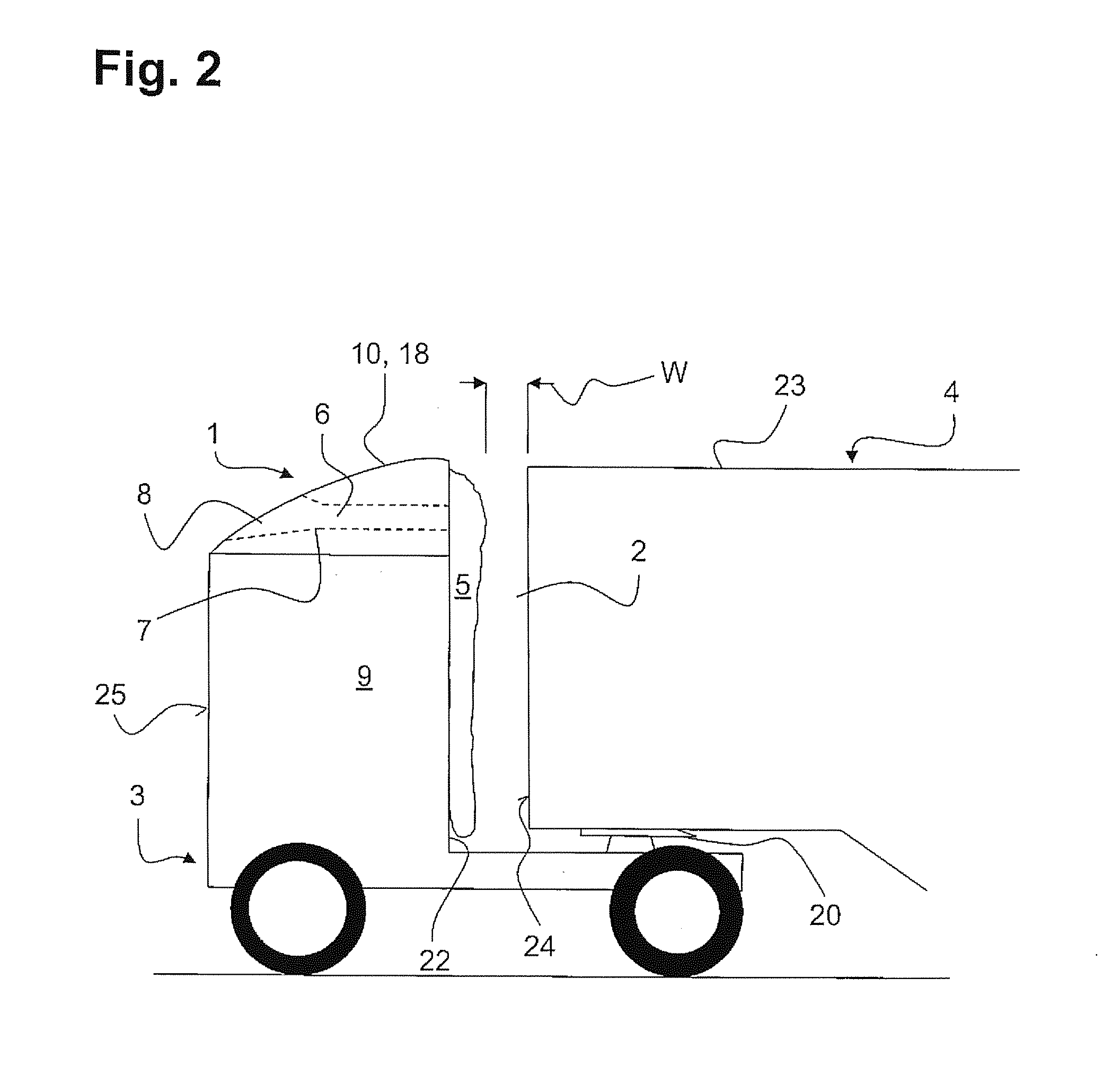
[0033]FIG. 1 shows the air guiding element 1 according to the invention, comprising an air cushion 5 and a filling channel 6 connected thereto, emerging at its front end in the direction of travel F on an upstream side 25 of the tractive vehicle 3. By upstream side is meant the contour of the tractive vehicle 3 facing the flow of the relative wind.

[0034]The air cushion 5 is arranged in a gap 2 between a tractive vehicle 3 and a trailer vehicle 4. The tractive vehicle 3 is an articulated vehicle, at whose rear end is situated a typical fifth wheel 20 as the coupling mechanism. The trailer vehicle 4, accordingly, is in the form of an articulated trailer and is detachably held in the fifth wheel 20 by means of a king pin (not shown) fastened to its underside.

[0035]The tractive vehicle 3 has a body 9, in which the driver's cabin among other things is accommodated. Above the body 9, furthermore, one notices a firmly mounted spoiler 18, which bounds the body 9 at the top in the manner of ...


PUM


Abstract

An air guiding element for improved flow over a gap between a tractive vehicle and a trailer vehicle is described, wherein the air guiding element can be mounted on the tractive vehicle or the trailer vehicle and has a flexible and airtight air cushion which is connected to a filling channel. The problem of providing a largely low-maintenance and operationally safe air guiding element, which can be installed independently of the compressed air supply of the tractive vehicle, for improved flow over the gap between a tractive vehicle and a trailer vehicle is addressed. The problem is solved by an air guiding element in which the filling channel has an air entry opening oriented in the direction of travel (F) on the side of the filling channel facing away from the air cushion, the air entry opening being arranged in such a way that the air cushion is filled exclusively by a dynamic pressure of the relative wind.

Description

FIELD OF THE INVENTION[0001]The invention concerns an air guiding element for improved flow over a gap between a tractive vehicle and a trailer vehicle, wherein the air guiding element can be mounted on the tractive vehicle or the trailer vehicle and comprises a flexible and airtight air cushion which is connected to a filling channel.BACKGROUND OF THE INVENTION[0002]During driving operation, the tractive vehicle and the trailer vehicle are constantly joined together mechanically by a coupling device. By a tractive vehicle and a trailer vehicle is meant a tractor-trailer combination, which usually consists of an articulated tractor as the tractive vehicle and an articulated trailer as the trailer vehicle. The two vehicles in this case are detachably coupled together by a coupling mechanism comprising a fifth wheel and a king pin. But the invention can also be implemented on an articulated vehicle consisting of a motor vehicle as the tractive vehicle and a trailer as the trailer vehi...

Claims


Application Information

Patent Timeline
Patent Type & Authority Applications(United States)
IPC IPC(8): B62D35/00
CPCB62D35/001
Inventor ALGUERA GALLEGO, JOSE MANUELRICHTER, MARTIN
Owner JOST WERKE
Learn More