Fault Detection in Subsea Power Cables

a technology of subsea power cables and fault detection, which is applied in the direction of fault location by conductor type, measurement devices, instruments, etc., can solve the problems of reducing the detection and finding of faults in medium to high voltage subsea cables, restricting the flow, and forming hydrates, so as to improve the detection of faults

a technology of subsea power cables and fault detection, which is applied in the direction of fault location by conductor type, measurement devices, instruments, etc., can solve the problems of reducing the detection and finding of faults in medium to high voltage subsea cables, restricting the flow, and forming hydrates, so as to improve the detection of faults

US20140361785A1Inactive Publication Date: 2014-12-11SIEMENS AG

Image

  • Fault Detection in Subsea Power Cables
  • Fault Detection in Subsea Power Cables
  • Fault Detection in Subsea Power Cables

Examples


Embodiment Construction

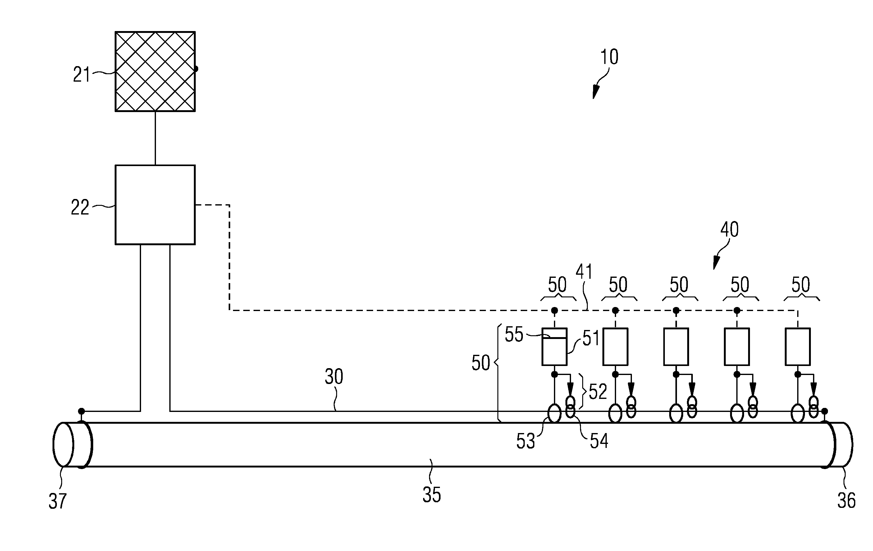
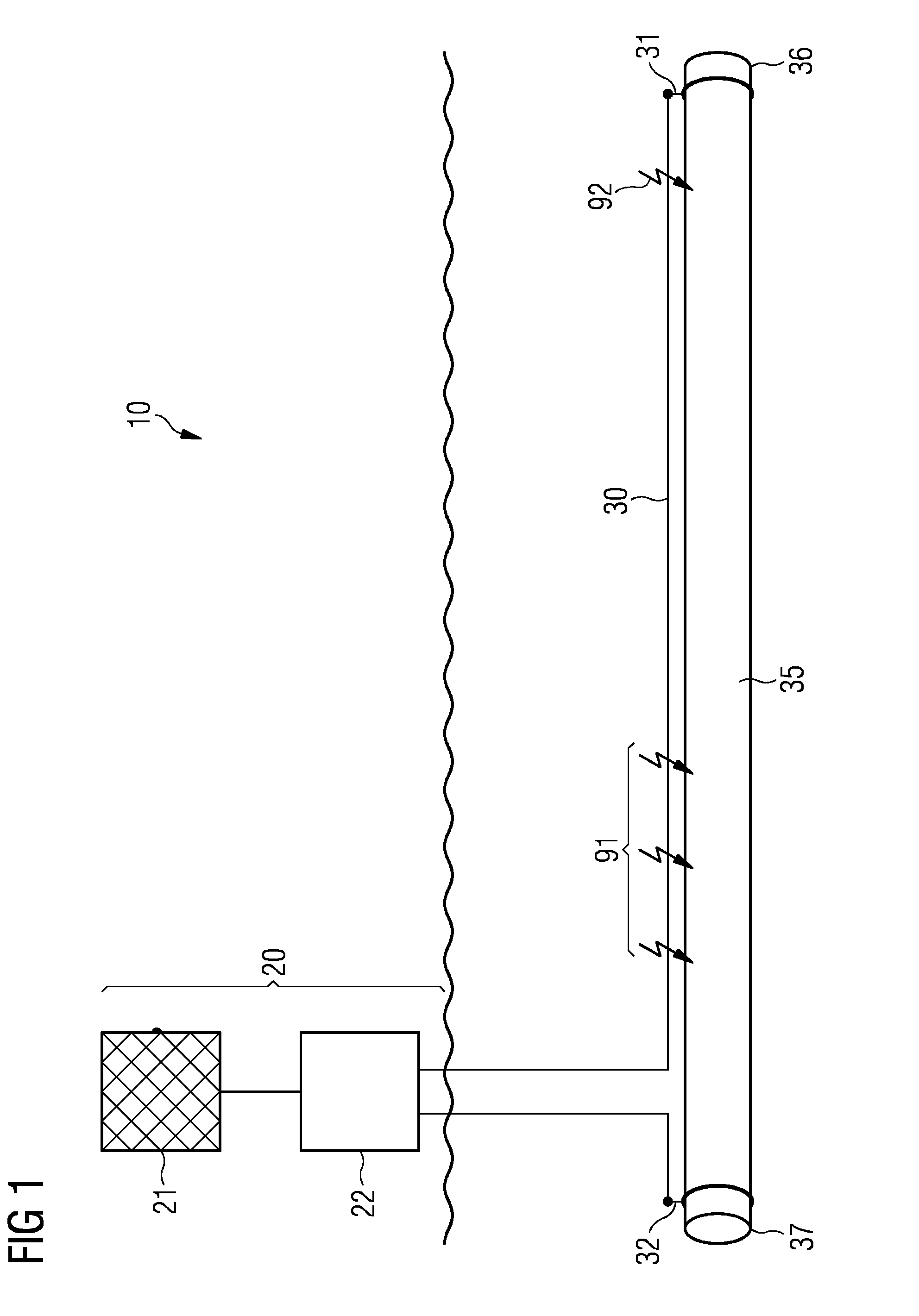
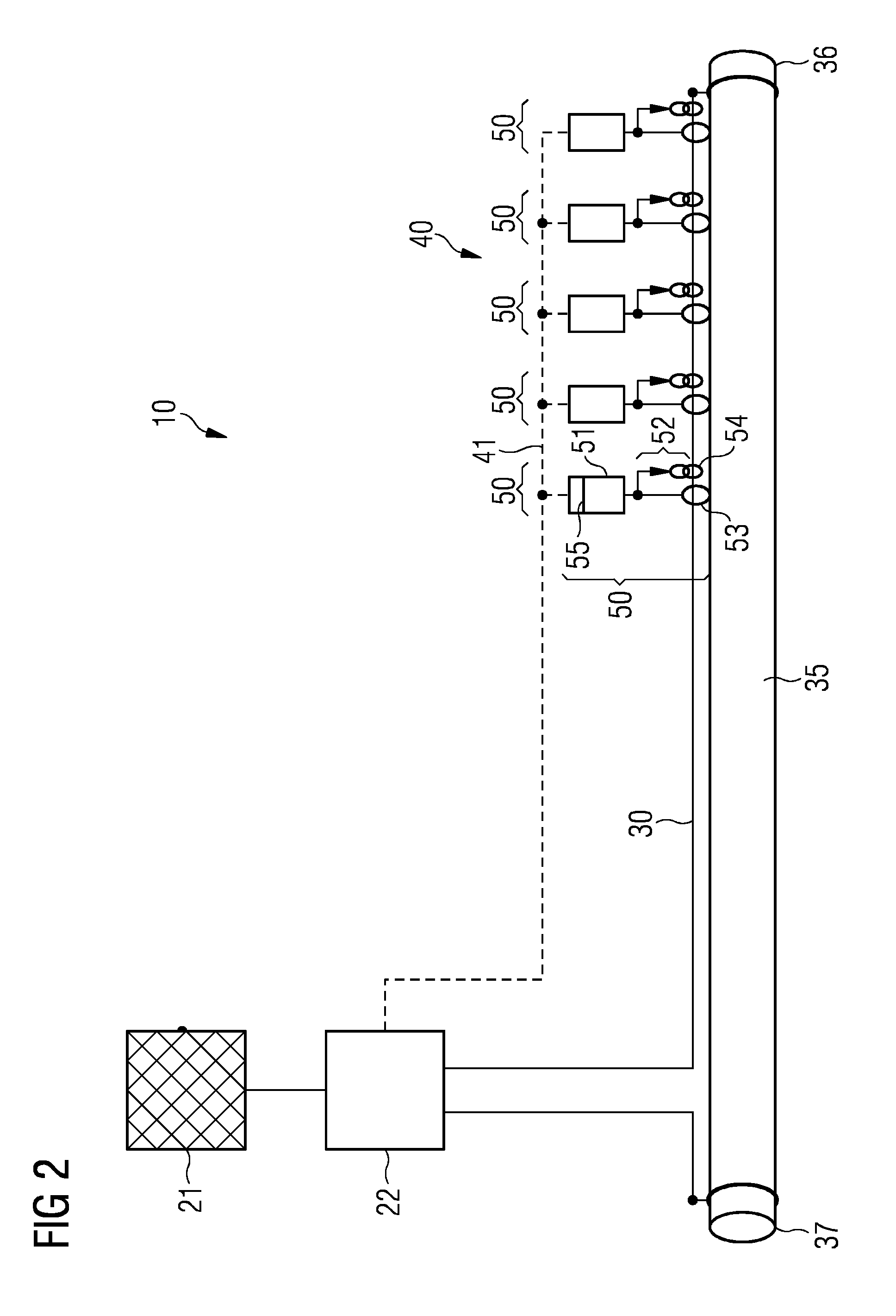
[0049]In the following, embodiments are described in detail with reference to the accompanying drawings. It is to be understood that the following description of embodiments is given only for the purpose of illustration and is not to be taken in a limiting sense.

[0050]It is noted that the drawings are schematic representations only, and elements in the drawings are not necessarily to scale with each other. Also, the coupling of physical or functional units as depicted in the drawings and described hereinafter does not necessarily need to be a direct connection or coupling, but may also be an indirect connection or coupling, e.g., a connection or a coupling with one or more additional intervening elements. A skilled person will further appreciate that the physical or functional units illustrated and described herein with respect to the different embodiments do not necessarily need to be implemented as physically separate units. One or more physical or functional blocks or units may b...


PUM


Abstract

A method of detecting a fault in a subsea power cable or in a direct electric heating system including a subsea power cable is provided. Measuring points are distributed along the subsea power cable. The method includes measuring at each measuring point a current in the subsea power cable and comparing the currents measured at the different measuring points.

Description

CROSS-REFERENCE TO RELATED APPLICATIONS[0001]The present patent document is a ยง371 nationalization of PCT Application Serial Number PCT / EP2013 / 051450, filed Jan. 25, 2013, designating the United States, which is hereby incorporated by reference, and this patent document also claims the benefit of EP 12000627.5, filed on Jan. 31, 2012, which is also hereby incorporated by reference.TECHNICAL FIELD[0002]The embodiments relate to fault detection in subsea power cables.BACKGROUND[0003]Recently, there has been an increasing interest in offshore hydrocarbon production. Hydrocarbon wells may be located many miles from shore sites and in water depths reaching down to several thousand meters. Subsea pipelines may be used for transporting hydrocarbons from an offshore well to a production vessel or to an onshore site, or may be used for transporting hydrocarbons between different onshore sites separated by an offshore section.[0004]In deep waters, the water temperature is relatively low (e.g....

Claims


Application Information

Patent Timeline
11 Dec 2014
Publication
US20140361785A1
IPC
G01R31/08; G01R25/00
CPC
G01R31/083; G01R31/021; G01R25/00; G01R31/085; H02H7/261; G01R31/58
Inventors
RADAN, DAMIR