System and method for inferring schematic relationships between load points and service transformers

Active Publication Date: 2014-12-11
POWER TAGGING TECH +1
View PDF13 Cites 34 Cited by
  • Summary
  • Abstract
  • Description
  • Claims
  • Application Information

AI Technical Summary

Benefits of technology

[0023]Another aspect of the invention is the composition of the locator pattern. The pre-determined locator pattern is known to the Receivers, and may consist of a sequence of one or more pure tones transmitted at known frequencies, or one or more gro

Problems solved by technology

Determining the supplying transformer by visual inspection is often difficult, as will be illustrated herein below.
Because existing service transformers are deployed in a variety of form-factors, and b

Method used


Image

  • System and method for inferring schematic relationships between load points and service transformers
  • System and method for inferring schematic relationships between load points and service transformers
  • System and method for inferring schematic relationships between load points and service transformers

Examples


first embodiment

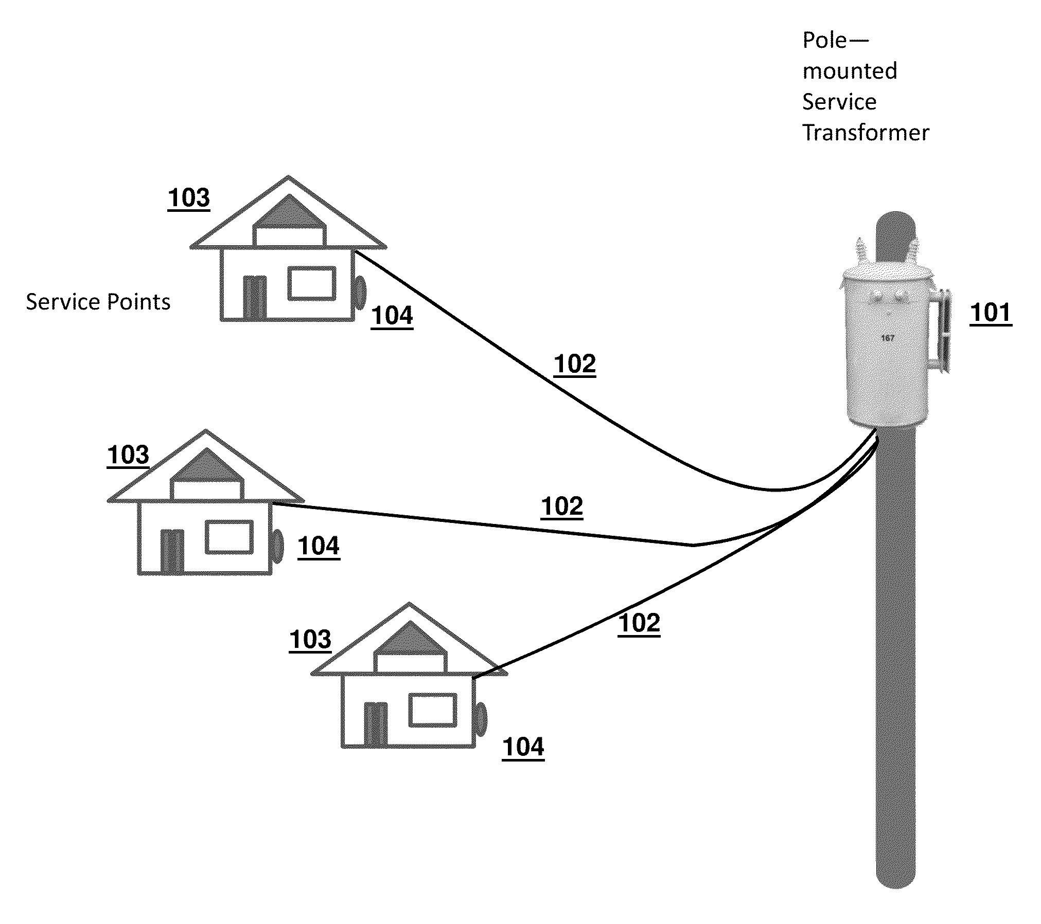
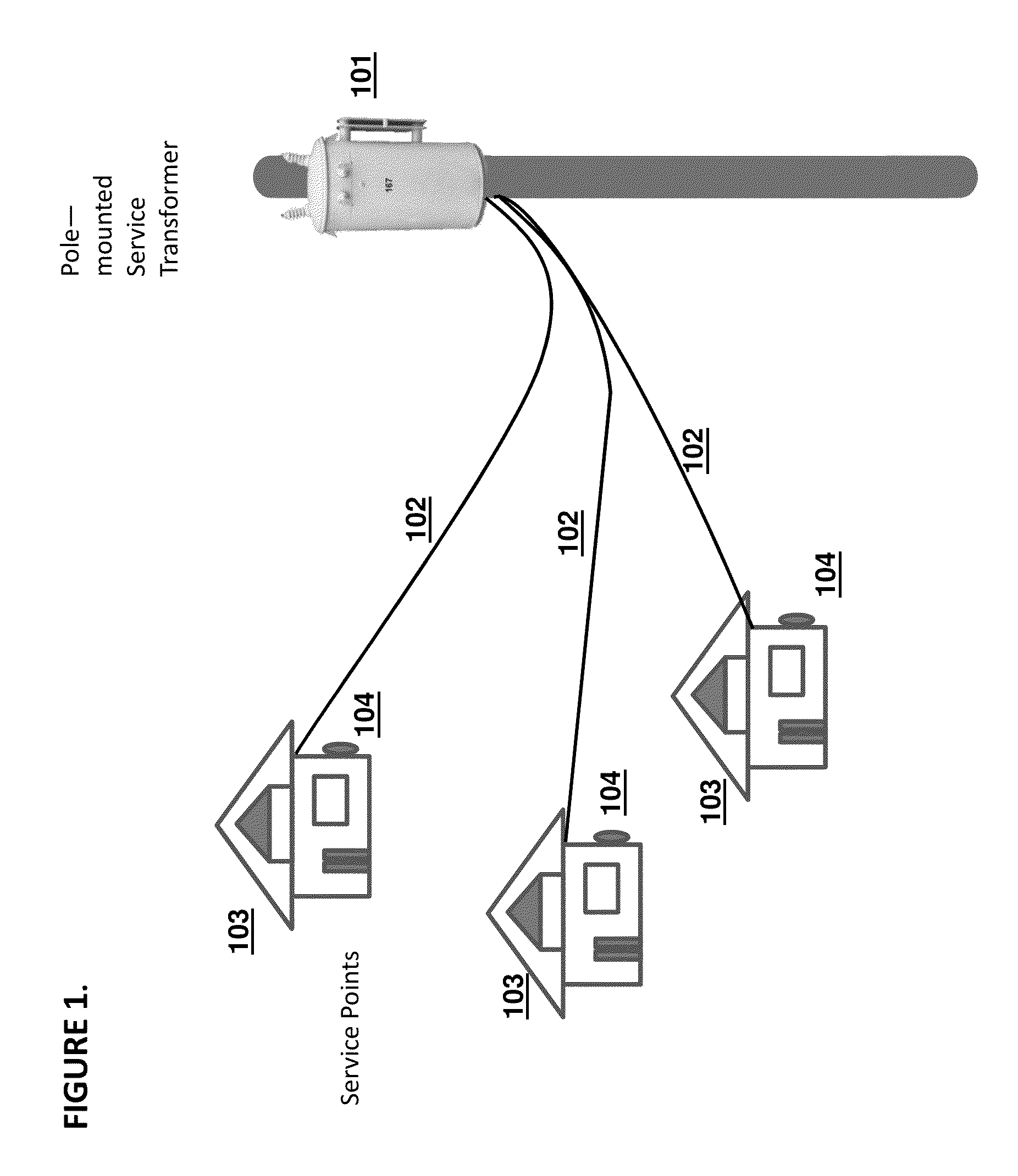
[0039]FIG. 5a depicts a Receiver device. Pole-mounted variant 502, comprising the components inside the dotted shape on FIG. 5a, clamps to the power pole, or to the housing of a pole-mounted transformer 501. This may be done using any type of clamping device, such as a spring-loaded clamp. It may be installed and removed using a hot-stick device to avoid the use of a “cherry picker” lift, which is more costly. The components of variant 502 may include clamp 503, antenna 504 for an optional wireless communication module, vibration sensor 505, and control unit 506. The vibration sensor 505 may be a contact or non-contact vibration sensor, such as, but not limited to, an accelerometer, directional microphone or laser vibrometer. The control unit may contain circuitry for recognizing a locator pattern, and it may also contain signal processing logic for demodulating data included in the signal. Additionally, the control unit may contain a communication module for transmitting detection ...

second embodiment

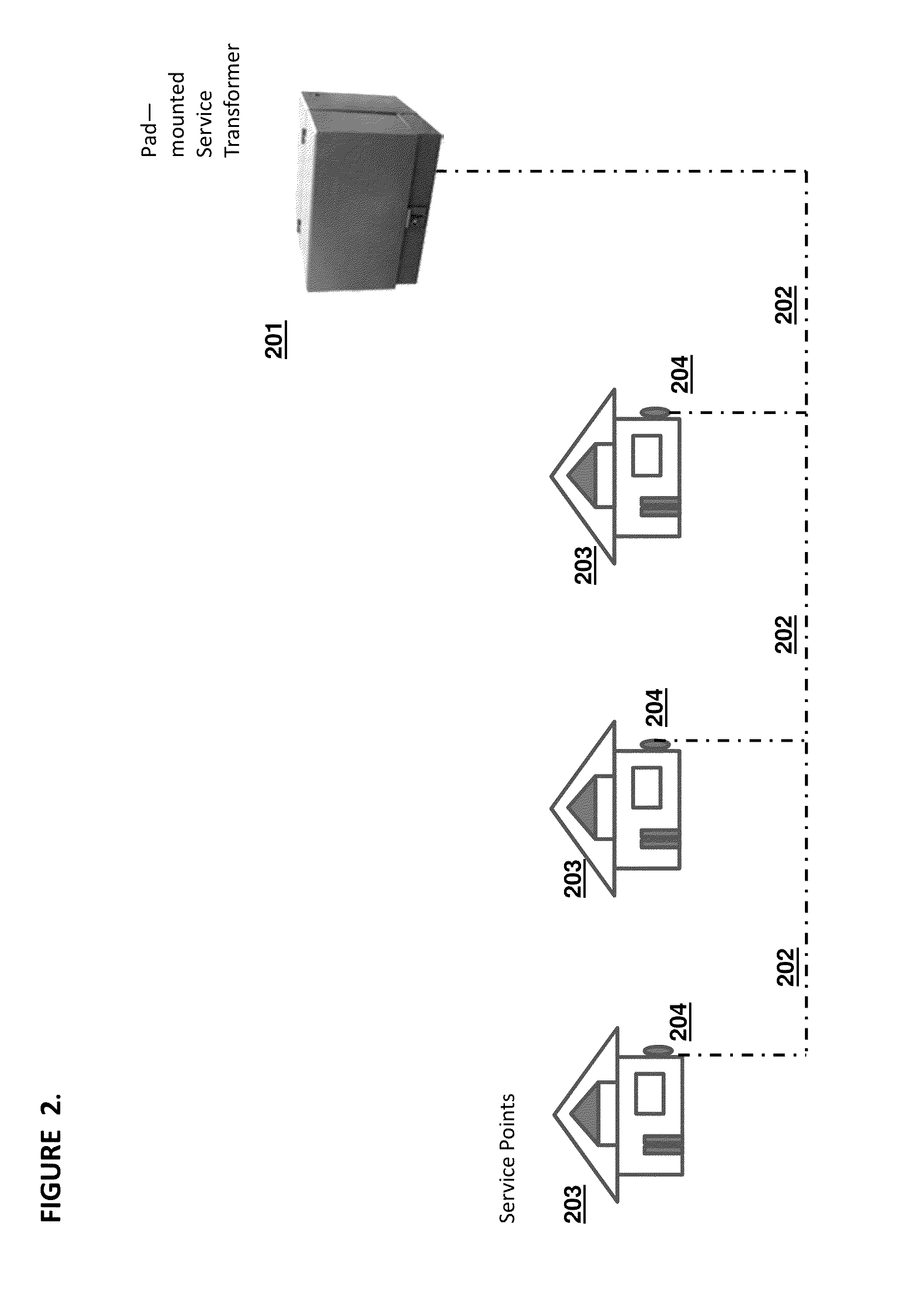
[0040]FIG. 5b depicts a receiver device. Receiver variant 511 is designed for use with pad-mounted transformers 510 having ferro-magnetic housings. The Receiver may adhere to the housing by means of attachment devices such as magnets 512, and detects locator patterns by means of vibration sensor 513, such as an accelerometer. Other attachment devices such as adhesives or suction cups may be substituted for magnets 512. Vibration sensor 513 may include a spring device to ensure strong mechanical contact with the housing. Antenna 516 is connected to a wireless communication module 515, which receives event notifications for wireless transmissions from a computation unit 514. The computation unit may also incorporate a memory unit for recording detection events. As with pole-mounted device 502, this unit may incorporate a variety of interface ports and display options.

third embodiment

[0041]FIG. 5c depicts a receiver device. In FIG. 5c, Receiver variant 517, comprising the components inside the dotted shape on FIG. 5c, is mounted on tripod 520. Receiver 517 may be detached from tripod 520 to be carried and aimed manually by a field engineer or installer. The Receiver consists of non-contact vibration sensor 518 and control unit 519. The non-contact vibration sensor 518 may be, but is not limited to, a laser vibrometer or directional microphone.

[0042]FIG. 6 shows an aerial view of an illustrative example of an urban residential neighborhood as is typical in the United States. The area comprises a grouping of older, Victorian era homes (607, 608) with separate carriage houses facing the alleyway, and modern infill housing (606) with attached garages and driveways facing the street. The neighborhood was electrified in several stages. First, power was provided to the original homes in the neighborhood via pole-mounted transformers. Electric pole 603 has three single-...


PUM


Abstract

A system and method for identifying which of several candidate service transformers is powering a specific service point an electrical distribution grid are disclosed. An audio-frequency electrical signal, the detection signal, is injected onto the power line at the service point via a meter socket or electrical outlet. The Transmitter for the detection signal may be a portable device or it may be incorporated into an electrical meter. The audible or mechanical resonance caused in the service transformer by the detection signal is detected and recorded using an accelerometer or directional microphone in a Receiver. A variety of methods for fixing the Receiver at or in proximity to the service transformers are disclosed in order to adapt to variations in the siting and housing of service transformers. A variety of mechanisms and methods for collecting detection events are disclosed.

Description


Claims


Application Information

Patent Timeline
IPC IPC(8): G01D4/00
CPCG01D4/002G01D2204/47H04B3/546H04B2203/5433H04B2203/5495Y04S20/30
Inventor BERNHEIM, HENRIK F.HANSELL, JERRITTMARTIN, MARCIA REIDBULLARD, JASON MARK
Owner POWER TAGGING TECH
Why Eureka
Try Eureka