Hose Holder and Method
a technology of hoses and holder plates, applied in the field of hose holders and methods, can solve the problems of dragging hoses across the parts of boats, destroying the finish, abraded boat surfaces, etc., and achieve the effect of small diameter
- Summary
- Abstract
- Description
- Claims
- Application Information
AI Technical Summary
Benefits of technology
Problems solved by technology
Method used
Image
Examples
second embodiment
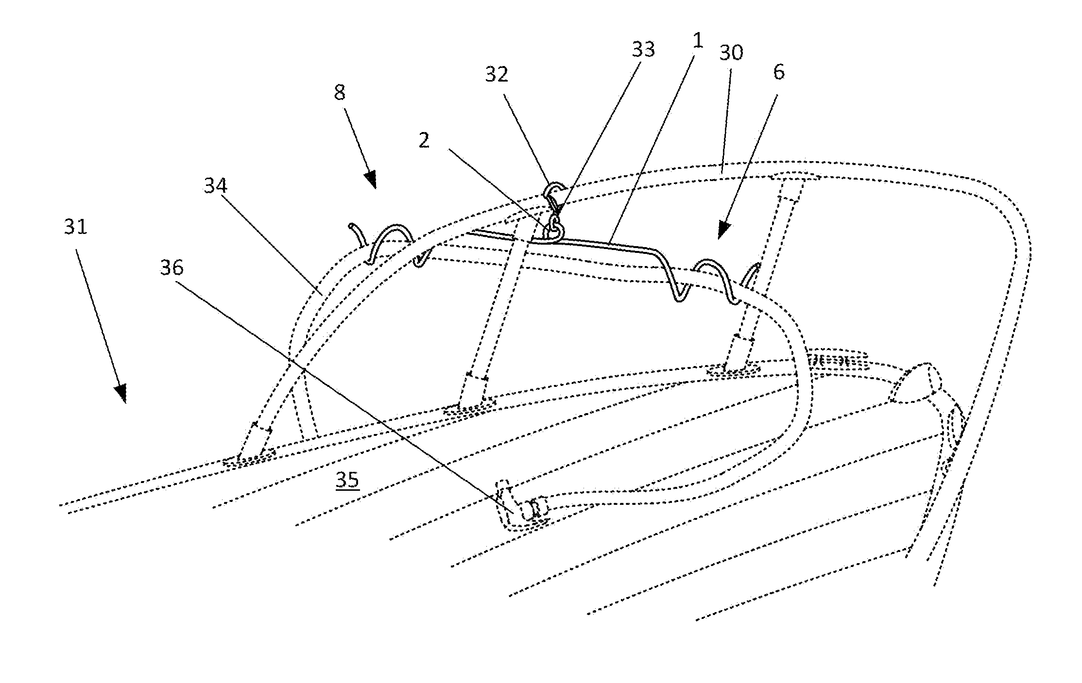
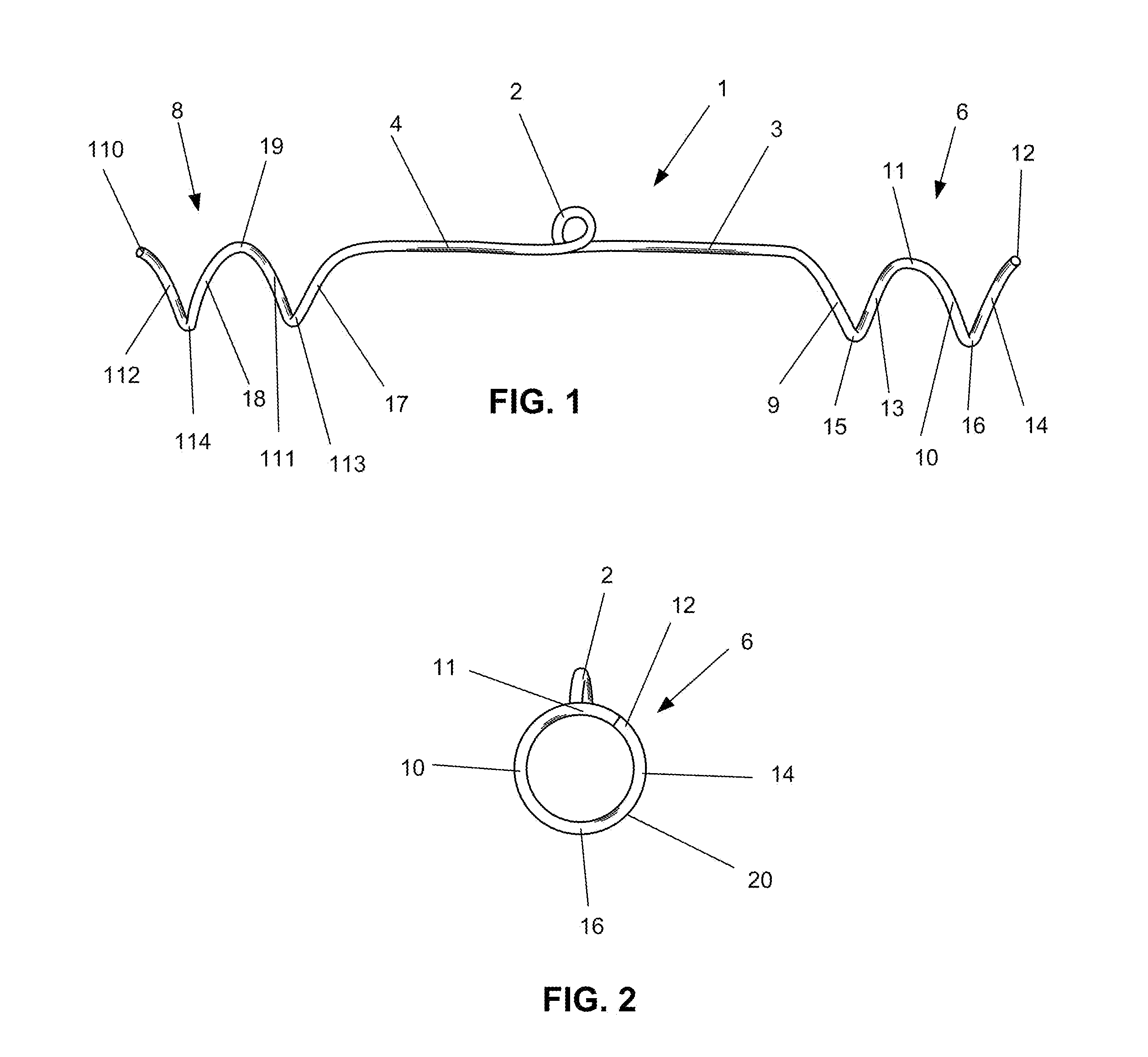
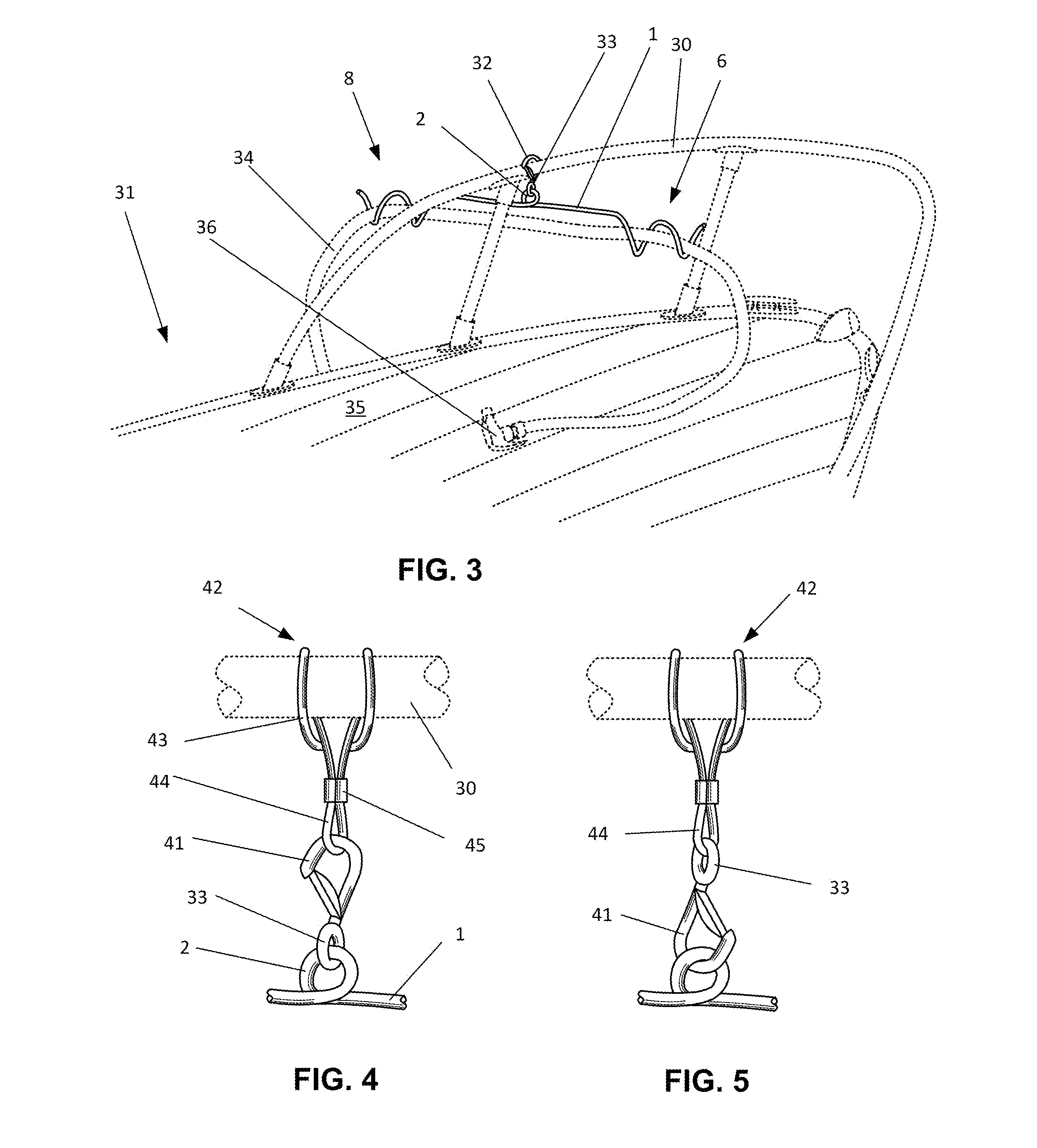
[0028]FIG. 3 is a view of the second preferred embodiment attached to the bow railing 30 of a boat 31. (The railing and the boat are shown in dashed lines to indicate environmental structure.) In this second embodiment, the invention includes a non-abrasive hook 32 as a means for attaching the loop 2 to the railing 30. A ring 33 at the bottom of the hook 32 flexibly engages the loop 2 in the rod 1 of the invention. A garden hose 34 has been inserted through the first helix 6 and the second helix 8 of the rod 1. In this way, the hose 34 may be pulled through the helices without rubbing against the edge of the foredeck 35. Note also that the first helix 6 serves as a catch for the spray nozzle 36 in the event that the weight of the hose 34 tries to pull the hose overboard.
[0029]FIG. 4 shows the significant parts distinguishing a third preferred embodiment of the invention from that shown in FIG. 3. This third preferred embodiment comprises the shaped rod 1 and the means for suspending...
fifth embodiment
[0034]FIG. 9 is a front view of the rod 1 portion of a fifth embodiment showing the first step of positioning a hose in it. In this embodiment, note that the second helix 8 rotates in the same sense as the first helix 6 as seen from the ends (in contrast to the preferred embodiments, in which the helices rotate in opposite senses as seen from the ends). While this embodiment functions the same way as the preferred embodiments once a hose is placed in it, placing a section of hose in it is significantly more difficult. This is a seven-step process, with the first step illustrated in FIG. 9. Here, a section 40 of hose 34 is placed so that the left end 51 of hose section 40 rests on the third lower limb 113 of the second helix 8 of the rod 1.
[0035]In FIG. 10, the second step involving the fifth embodiment, the left end 51 of the hose section 40 is lifted into position in front of the fourth rearward limb 112 of the second helix 8.
[0036]Next, FIG. 11 shows the third and fourth steps in ...
sixth embodiment
[0041]FIG. 15 is a perspective view of the instant invention. Shaped rod 1 is flexibly suspended from a staff 150 by an eye bolt 151. The staff 150 is of a length sufficient to suspend a hose above a cylindrical cavity in a boat or other object. The staff 150 depicted here is equipped with a male gimbal fishing rod end 152 specially adapted to fit rotatably in a fishing rod holder (not shown in this view—see FIG. 17).
[0042]FIG. 16 is a perspective view of the rod end 152 of the staff 150 of the sixth embodiment. Note the four obround cavities 160 which are shaped to engage pins within a typical fishing rod holder (see FIG. 17).
[0043]FIG. 17 is a perspective view of the staff 150 of the sixth embodiment placed in a typical fishing rod holder 170 located on a gunwale 171 of a boat 172. A hose 34 held by this embodiment stays well clear of the gunwale 171. (The boat 172 and appurtenances and the hose 34 are shown in dashed lines as environmental structure.)
PUM
 Abstract
Description
Claims
Application Information
 - R&D
- Intellectual Property
- Life Sciences
- Materials
- Tech Scout
- Unparalleled Data Quality
- Higher Quality Content
- 60% Fewer Hallucinations
Browse by: Latest US Patents, China's latest patents, Technical Efficacy Thesaurus, Application Domain, Technology Topic, Popular Technical Reports.
© 2025 PatSnap. All rights reserved.Legal|Privacy policy|Modern Slavery Act Transparency Statement|Sitemap|About US| Contact US: help@patsnap.com


