
Filter apparatus

a filter element and filter element technology, applied in the field of filter apparatus, can solve the problems of increased fluid flowing from the inside to the outside difficult to filter the target fluid, and matter adhering to the filter element is not completely removed, so as to improve the backwashing efficiency of the filter element, reduce the number of parts, and simplify the structure of the backwashing structure

Active Publication Date: 2014-12-18
FUJI FILTER MFG
View PDF1 Cites 16 Cited by
  • Summary
  • Abstract
  • Description
  • Claims
  • Application Information

AI Technical Summary

Benefits of technology

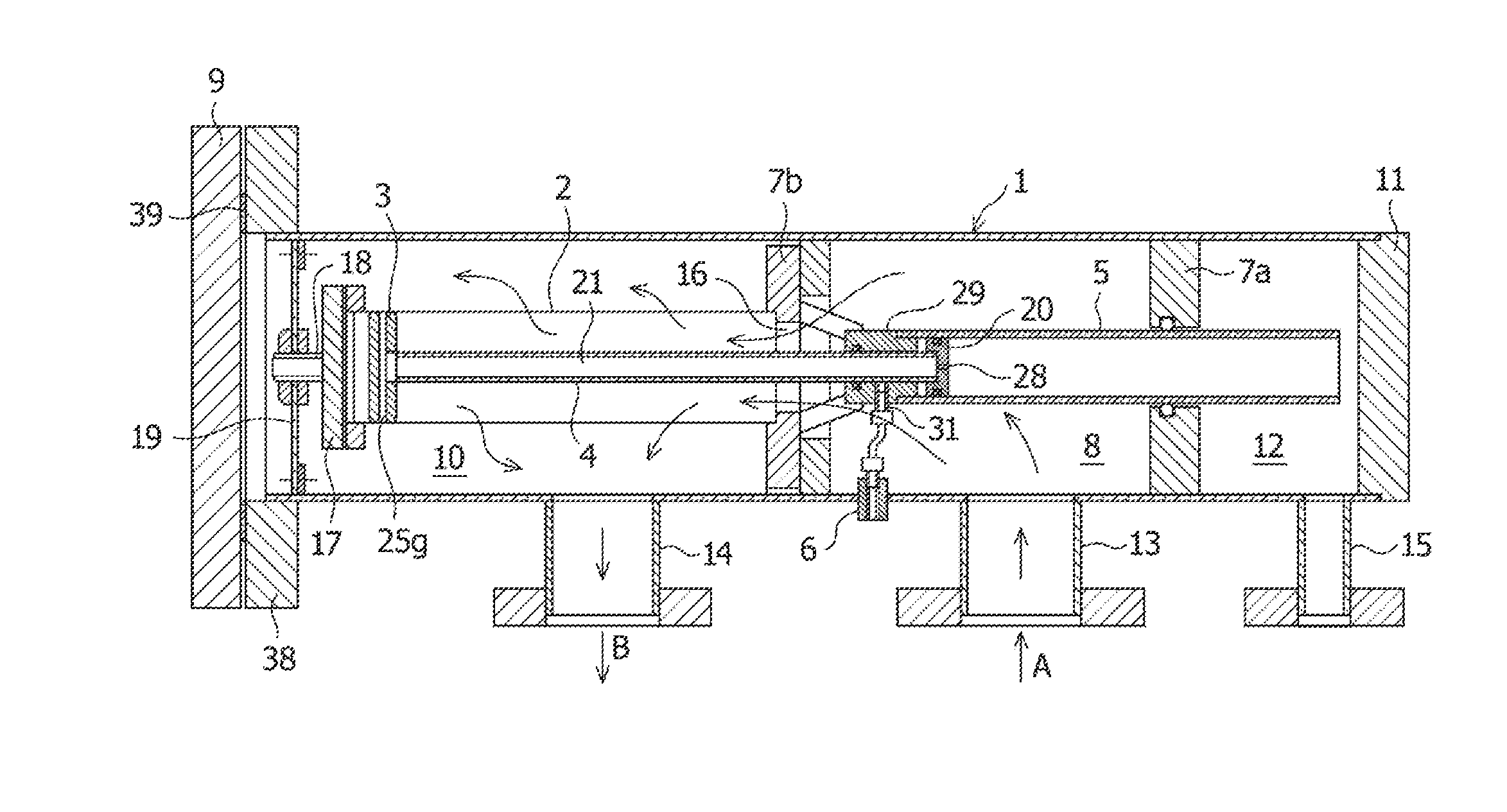
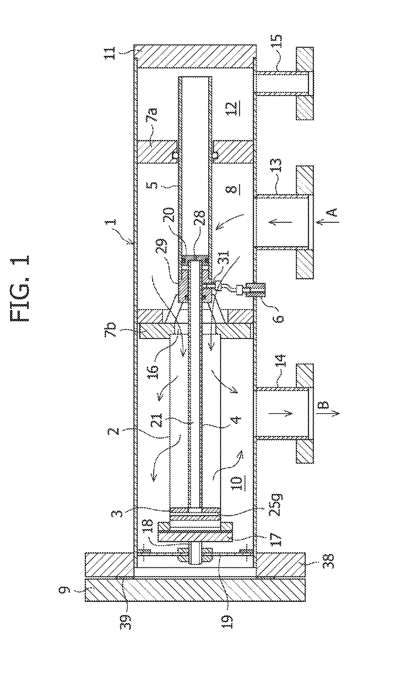
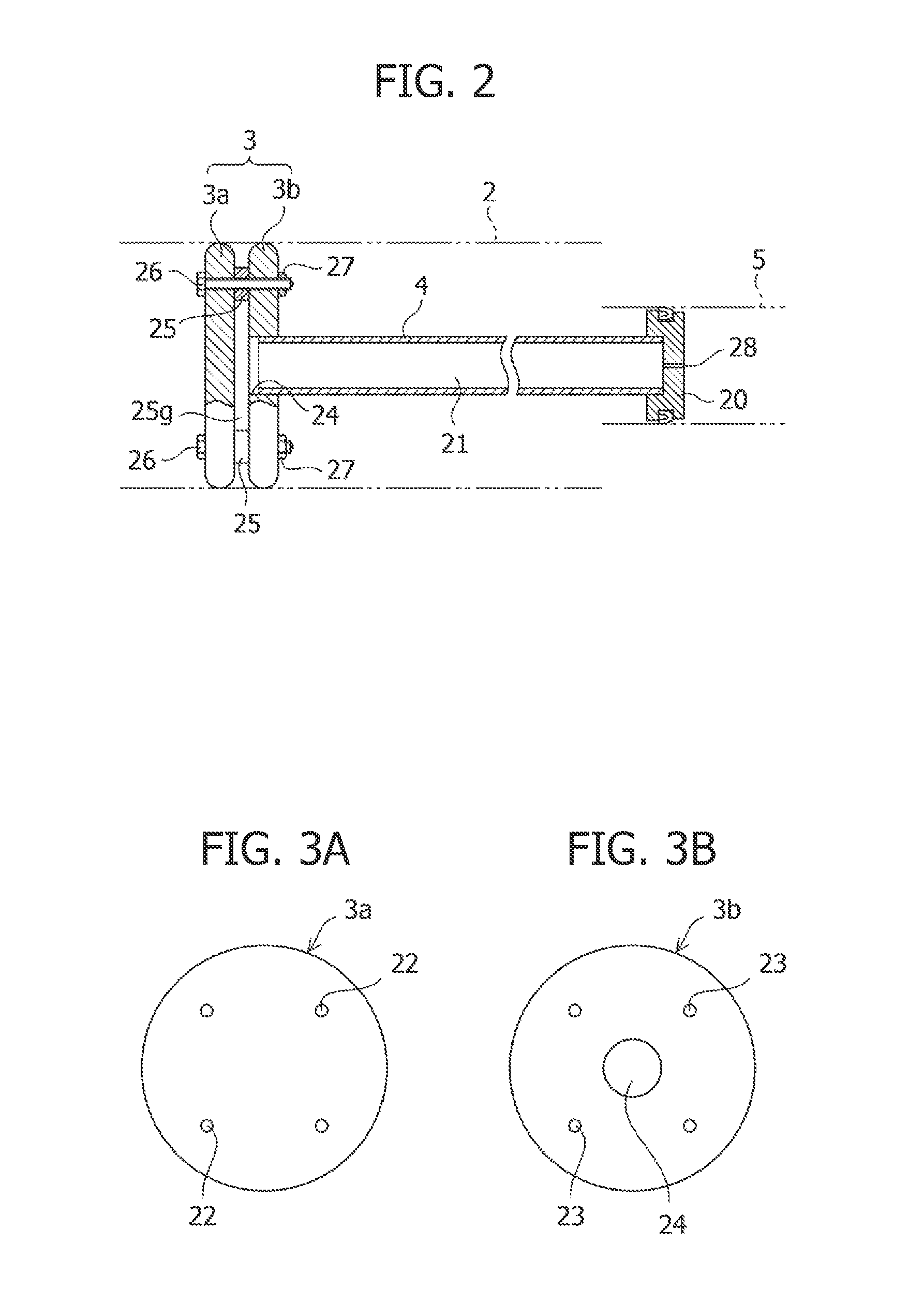
The present invention provides a filter apparatus that allows for efficient backwashing, which removes trapped matter adhering to the inner surface of the filter element due to filtration. The apparatus includes a filter element with a backwash slide member that can move backward and forward inside the filter element to remove trapped matter. The backwash pipe has an aperture portion with a smaller opening than the cross-sectional area of the fluid flowing passage, which allows the inward flow generated during backwashing to flow out towards the drain chamber. The apparatus also includes a fluid flowing unit that allows fluid to flow in and out of the actuation cylinder, in which the piston member of the backwash pipe moves backward and forward. By arranging multiple filter units in parallel, the processing rate of filtration can be increased, and the drain rate and backwash efficiencies can be improved. Additionally, a larger filtration area can be obtained with the same capacity.

Problems solved by technology

When filtration is performed by the filter apparatus for a long time, solid matter, accreted dust, and the like trapped on a filter element accumulate on the filter element, so that resistance of a fluid flowing from an inside to an outside of the filter element increases, and this ultimately makes the fluid to be filtered (target fluid) difficult to filter.
However, there may be a case in which the trapped matter adhering to the filter element is not removed completely and remains.
In this case, even with repeated backwashing, the resistance of the fluid flowing from the inside to the outside of the filter element increases, and the target fluid becomes difficult to be filtered.
In particular, as in a case of filtration of liquid, when accreted dust, dust covered with highly adhesive materials, and the like firmly adhere to a surface of the filter element, it is difficult to restore filtering performance of the filter element only by the backwashing making the fluid pass through the filter element in the reverse direction of the filtering direction.

Method used


Image

  • Filter apparatus
  • Filter apparatus
  • Filter apparatus

Examples


second embodiment

[0096]FIG. 7 is an enlarged cross-sectional view of a main part illustrating the backwash slide member 3. In the present embodiment, a brush 34 which slides in contact with the inner circumferential surface of the filter element 2 over the entire circumference thereof is provided along an outer circumferential portion of one side surface or each of side surfaces of the disk-shaped members (3a, 3b). This brush 34 moves together with the backwash slide member 3 when the backwash slide member 3 moves backward and forward inside the filter element 2 in the axial direction of the filter element 2, to scrape away trapped matter adhering to the inner circumferential surface of the filter element 2. As illustrated in FIG. 7, the brush 34 is formed by attaching brush bristles 34b to an outer circumferential portion of a channel ring 34a and is called a ring brush. The channel ring 34a is made of a channel material, made of, for example, a metal, having a substantially U-shaped cross-section,...

third embodiment

[0099]FIG. 8 is an enlarged schematic view of a main part illustrating the backwash slide member 3. In the present embodiment, at least one fluid passing opening (35, 36) penetrating from one side surface to the other side surface is arranged on the disk surfaces of the disk-shaped members (3a, 3b) and on a portion except for a connecting portion with the fluid flowing passage 21. That is, in a state in which the gap 25g is formed between the first disk-shaped member 3a and the second disk-shaped member 3b, the fluid passing openings 35, 36 penetrating through the first disk-shaped member 3a and the second disk-shaped member 3b are formed. In this case, the fluid passing openings 35, 36 do not communicate with the fluid flowing passage 21 illustrated in FIG. 2.

[0100]FIGS. 9A to 9D illustrate shapes and structures of the first and second disk-shaped members 3a, 3b in the backwash slide member 3 according to the third embodiment. FIG. 9A is a left side view of the first disk-shaped me...


PUM

PropertyMeasurementUnit
pore sizeaaaaaaaaaa
pressureaaaaaaaaaa
pressureaaaaaaaaaa

Abstract

A filter apparatus including: a casing including, in a sealed space provided therein, a fluid inflow chamber, a filtration chamber and a drain chamber; a filter element provided inside the filtration chamber to let a fluid pass therethrough from inside to outside to perform filtration; a backwash slide member movably provided inside the filter element and removing trapped matter adhering to an inner circumferential surface of the filter element by an inward flow generated by a difference in pressure inside and outside the filter element at the time of backwashing; a backwash pipe that lets the inward flow flow toward the drain chamber; an actuation cylinder that lets the fluid from the backwash pipe flow toward the drain chamber; and a fluid flowing unit allowing a fluid to flow, enabling a piston member to move inside the actuation cylinder.

Description

TECHNICAL FIELD[0001]The present invention relates to a filter apparatus enabling backwashing, which removes trapped matter adhering to an inner circumferential surface of a cylindrical filter element provided inside a filtration chamber, and more specifically relates to a filter apparatus with a simplified structure for the backwashing, which removes the trapped matter adhering to the inner circumferential surface of the filter element due to filtration, and the filter apparatus capable of improving backwash efficiencies of the filter element.BACKGROUND ART[0002]Conventionally, in a filtration process of liquid for general industrial use such as cooling water for various apparatuses or process liquid, a filtration process of oil such as lubricating oil and diesel fuel oil, and a filtration process of gas and the like of various raw materials for use in a chemical plant and the like, various filter apparatuses are used for the purpose of trapping and removing fine particles, dust, a...

Claims


Application Information

Patent Timeline
Patent Type & Authority Applications(United States)
IPC IPC(8): B01D29/68B01D29/23B01D46/00B01D29/64B01D29/52
CPCB01D29/684B01D29/6423B01D29/52B01D46/002B01D46/0065B01D29/23B01D46/0071B01D29/117B01D29/688B01D46/681B01D46/682B01D46/2403B01D46/58B01D46/72
Inventor TAKAHASHI, YUICHI
Owner FUJI FILTER MFG
Learn More