Inkjet marking module and method for conditioning inkjet marking module

a technology of inkjet printing and marking module, which is applied in the direction of printing, other printing apparatus, etc., can solve the problems of deterioration of jetting properties of inkjet printing devices (inkjet head of printhead), inability of humidity sensors to prevent super-saturation or even condensation, and achieve accurate control of vapor pressur

Active Publication Date: 2014-12-18
OCE TECH
View PDF1 Cites 20 Cited by
  • Summary
  • Abstract
  • Description
  • Claims
  • Application Information

AI Technical Summary

Benefits of technology

[0011]It is an object of the present invention to provide an inkjet marking module suitable for accurately controlling the vapor pressure of a solvent vapor in a gaseous medium, in particular close to the saturated vapor pressure of said solvent vapor in the gaseous medium, in the nozzle region of an inkjet marking device (e.g. printhead), thereby solving or at least mitigating the disadvantages as described above.

Problems solved by technology

Deterioration of jetting properties of an inkjet printing device (inkjet head of printhead) is a known problem in the background art.
It is also known that nozzle clogging of inkjet heads with dried ink residues and depositions of dried ink residues on a nozzle plate near the nozzles cause jetting properties to deteriorate.
A disadvantage of the humidifying methods and devices as disclosed in U.S. Application Publication No. 2007 / 0285456 and U.S. Application Publication No. 2011 / 0115863 is that humidity sensors are not capable of preventing super-saturation or even condensation if the RH to be controlled (setpoint of the humidity sensor) deviates from 100% (e.g. saturation) by less than the accuracy of the humidity sensor.
Therefore, adequate control of a RH near the saturation point while preventing supersaturation and / or condensation is not possible.
It is another disadvantage of the humidifying methods and devices as disclosed in U.S. Application Publication No. 2007 / 0285456 and U.S. Application Publication No. 2011 / 0115863 that directly controlling the air humidity based on humidity sensing is too slow in a high speed printing process, such that the air humidity in the nozzle region is not properly controlled, which may lead to drying out of ink residues and hence to nozzle clogging or to condensation, both deteriorating the jet properties.
It is yet another disadvantage of the humidifying method and device as disclosed in U.S. Application Publication No. 2007 / 0285456 that the arrangement of the humidity sensor is such that the relative humidity in a region near the nozzles is only periodically measured, when the ink carriage comprising the ink cartridge passes the humidity sensor.
Continuous and accurate humidity control is therefore not possible.

Method used


Image

  • Inkjet marking module and method for conditioning inkjet marking module
  • Inkjet marking module and method for conditioning inkjet marking module
  • Inkjet marking module and method for conditioning inkjet marking module

Examples


Embodiment Construction

[0076]The present invention will now be described with reference to the accompanying drawings wherein the same or similar elements have been identified with the same reference numerals.

Printing Process

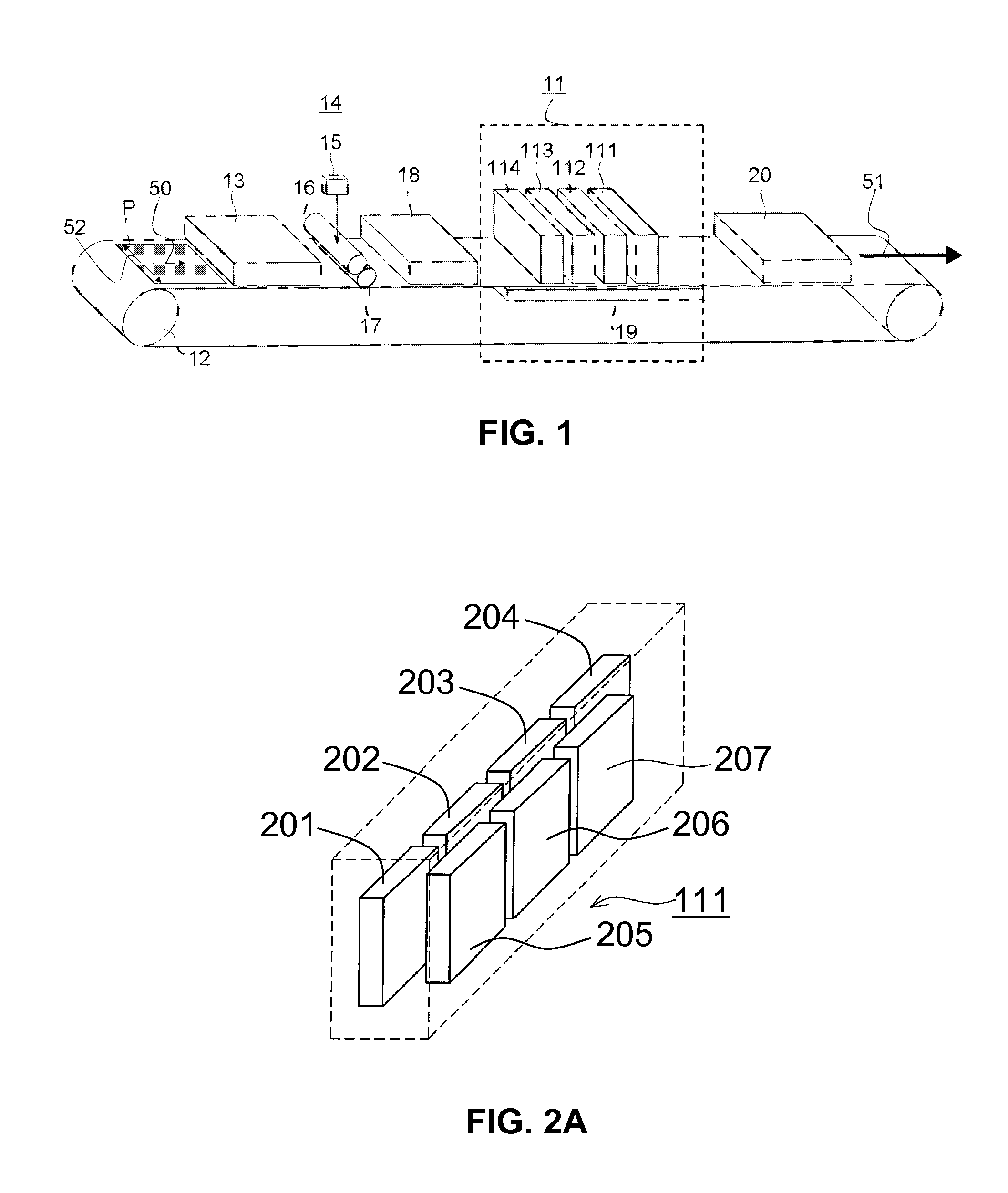
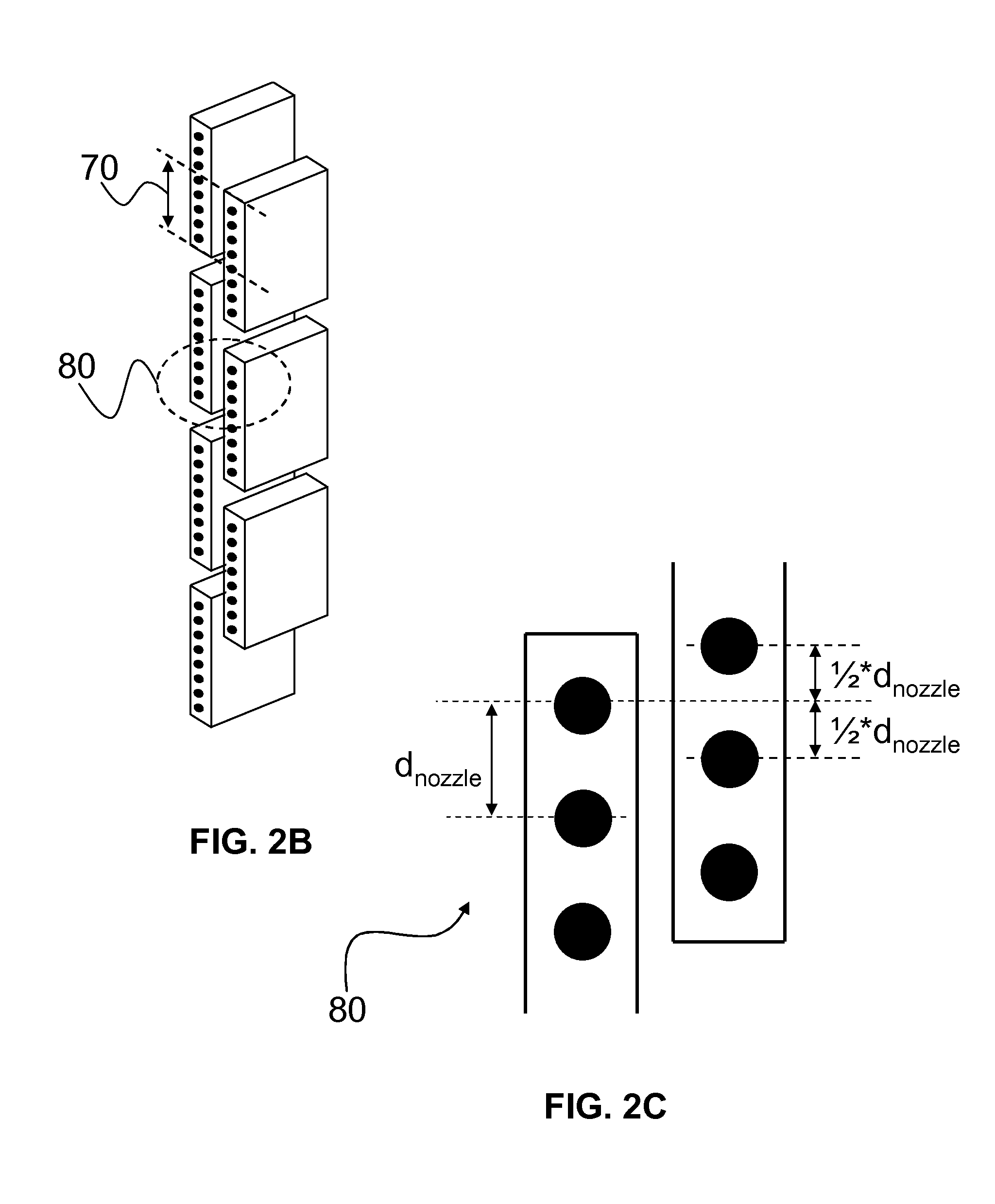
[0077]A printing process in which the inks according to the present invention may be suitably used is described with reference to the appended drawings shown in FIG. 1 and FIGS. 2A-2C. FIGS. 1 and 2A-C are schematic representations of an inkjet printing system and an inkjet marking device, respectively.

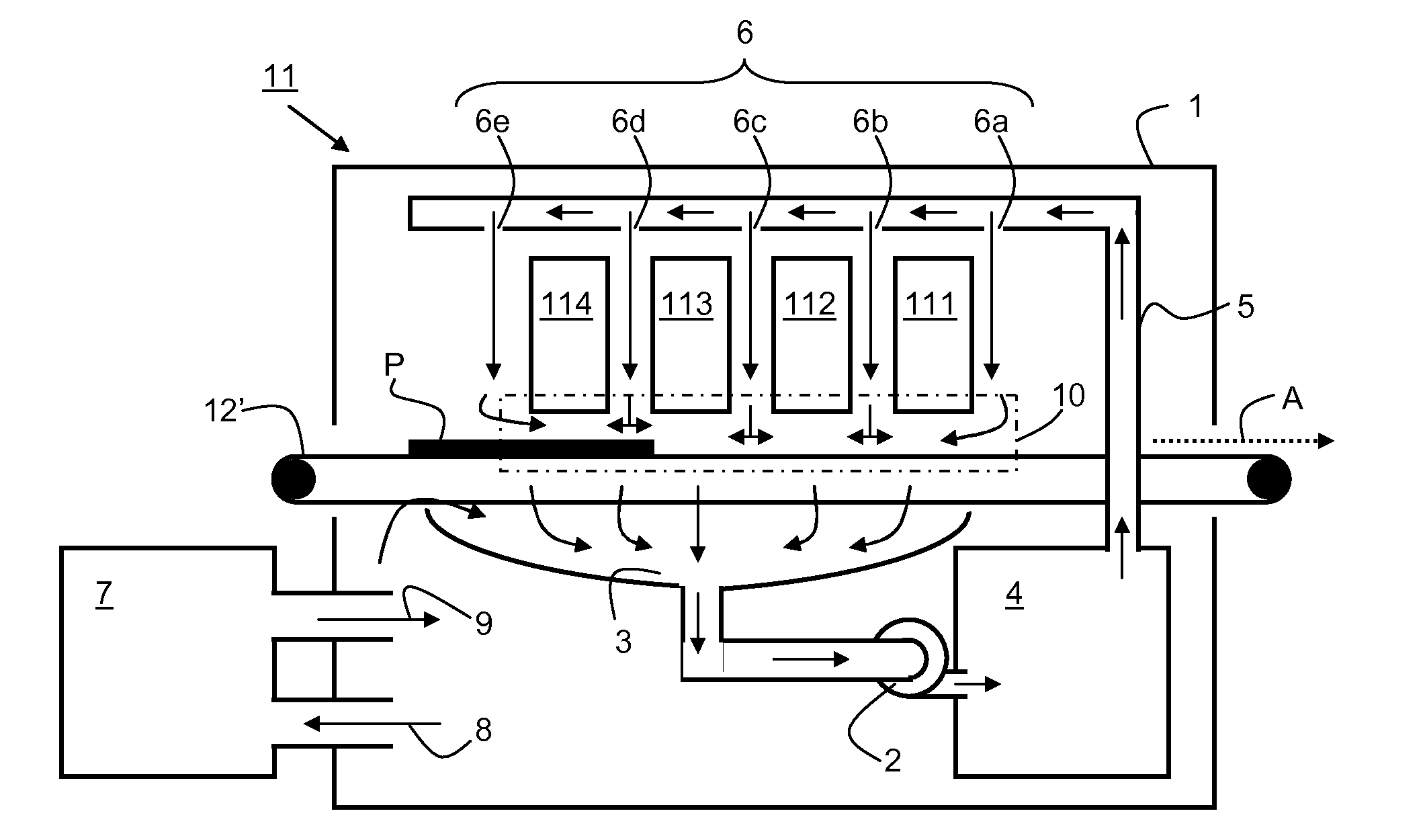
[0078]FIG. 1 shows that a sheet of a receiving medium, in particular a machine coated medium P, is transported in a direction for conveyance as indicated by arrows 50 and 51 and with the aid of transportation mechanism 12. Transportation mechanism 12 may be a driven belt system comprising one (as shown in FIG. 1) or more belts. Alternatively, one or more of these belts may be exchanged for one or more drums. A transportation mechanism may be suitably configured depending on the requireme...


PUM


Abstract

An inkjet marking module includes an inkjet marking device adapted to jet droplets of an inkjet marking material to form an image on recording substrate; and an evaporation device arranged for evaporating a solvent to a gaseous medium. The evaporation device includes an aerosol generator for creating an aerosol of the solvent in the gaseous medium; and a droplet eliminator for removing droplets from the aerosol, the droplet eliminator being arranged downstream of the aerosol generator. A printing system includes such an inkjet marking module and a method is disclosed for controlling the relative degree of saturation of a solvent vapor in a gaseous medium in an inkjet marking module.

Description

CROSS-REFERENCE TO RELATED APPLICATIONS[0001]This application is a Continuation of International Application No. PCT / EP2013 / 053563, filed on Feb. 22, 2013, and for which priority is claimed under 35 U.S.C. §120. PCT / EP2013 / 053563 claims priority under 35 U.S.C. §119(a) to Application No. 12157848.8, filed in Europe on Mar. 2, 2012. The entire contents of each of the above-identified applications are hereby incorporated by reference into the present application.BACKGROUND OF THE INVENTION[0002]1. Field of the Invention[0003]The present invention relates to an inkjet marking module comprising an inkjet marking device being adapted to jet droplets of an inkjet marking material to form an image on recording substrate; and an evaporation device arranged for evaporating a solvent in a gaseous medium, the evaporation device being arranged to control the vapor pressure of a solvent vapor in a gaseous medium present in the printing module within a predetermined range in order to prevent dryi...

Claims


Application Information

Patent Timeline
Patent Type & Authority Applications(United States)
IPC IPC(8): B41J2/165
CPCB41J2002/16555B41J2/16552B41J2/165B41J11/0085B41J2/1714
Inventor LA VOS, PETER G.GROENENBERG, CORNELIS J.
Owner OCE TECH
Why Eureka
Try Eureka