Solid state light sources with common luminescent and heat dissipating surfaces

a technology of luminescent and heat dissipation surface, which is applied in the direction of semiconductor devices, light sources, lighting and heating equipment, etc., can solve the problems of degrading the optical properties of materials, and achieve the effect of low cost and low cos

Active Publication Date: 2014-12-18
GOLDENEYE
View PDF2 Cites 17 Cited by
  • Summary
  • Abstract
  • Description
  • Claims
  • Application Information

AI Technical Summary

Benefits of technology

The patent describes a new type of LED light source that uses thermally conductive elements to efficiently cool the LEDs. The electrical interconnect to the LEDs can be integrated onto the thermally conductive elements, which can reflect and recycle light emitted by the LEDs. The use of lower light transmitting materials allows for more efficient cooling, while higher thermal conductivity materials reduce thermal resistance and enable more efficient cooling. The non-flammable solid state light sources based on LEDs mounted on thermally conductive elements provide a safer alternative to traditional light sources and can be easily embedded in suspended ceilings or power grids. The invention offers a cost-effective solution for cooling LEDs and other semiconductor devices.

Problems solved by technology

The techniques to reduce the fire hazard of organics cannot meet Class 1 or Class A requirements due to flame spread and smoke but also degrade optical properties of the materials.

Method used


Image

  • Solid state light sources with common luminescent and heat dissipating surfaces
  • Solid state light sources with common luminescent and heat dissipating surfaces
  • Solid state light sources with common luminescent and heat dissipating surfaces

Examples


Embodiment Construction

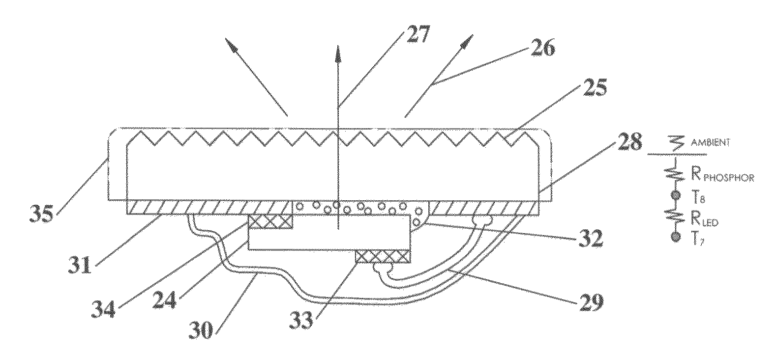
[0088]According to the present invention as practiced herein, a conductive interconnect (transparent or reflective) is deposited on translucent thermally conductive elements (e.g. alumina (Al2O3), transparent alumina (TPA), Spinel, Sapphire, etc.) This can be done lithographically, or more preferred, via screen printing. LEDs or LEDs on surface mountable ceramic substrates (also referred herein as LED packages) are mounted (e.g. via soldering or conductive adhesives) to the interconnect on the translucent thermally conductive elements. It is preferred that the mounting method establish a low thermal resistant contact from the LED to the light transmitting thermally conductive element. Light emitted by the LEDs is directed to the thermally conductive translucent elements where it passes through and is emitted by the thermally conductive light transmitting (and thereby light emitting luminescent) element. The light transmitting thermally conductive elements have surface areas sufficie...


PUM


Abstract

A solid-state light source with LEDs contained in a light recycling cavity emits both light and heat from heat extracting light emitting elements which form the light recycling cavity. Eliminating appended heat sinks makes these light sources ultra lightweight. The light sources can be attached and supported by suspended ceilings without affecting the seismic properties of the ceiling. The heat extracting light emitting elements are combined with a reflector to make directional light sources, which can be attached to ceilings with small magnets. Because the heat extracting light emitting elements transfer the heat from the light source to the illuminated area there is no requirement for disturbing or penetrating the ceiling barrier to a heat sink on the plenum side of the ceiling. This enables a contiguous acoustic ceiling. Further, the light sources are made from non flammable materials and therefore do not affect the fire rating of the ceiling.

Description

CROSS-REFERENCE TO RELATED APPLICATIONS[0001]This application is a continuation of U.S. application Ser. No. 14 / 042,569 filed on Sep. 30, 2013, which is a continuation in part of U.S. application Ser. No. 13 / 572,608 filed on Aug. 10, 2012, which claims benefit of U.S. Provisional Application Ser. No. 61 / 574,925, filed on Aug. 11, 2011, which is herein incorporated by reference. This application also claims the benefit of U.S. Provisional Patent Application No. 61 / 957,768, filed Jul. 10, 2013, which is also herein incorporated by reference.BACKGROUND OF THE INVENTION[0002]Solid State light sources based on light emitting diode (LED) technology offer the promise of energy savings over incandescent and fluorescent lighting without the toxic materials utilized in fluorescent or organic light emitting diode (OLED) light sources.[0003]However to achieve widespread adoption and acceptance of solid state lighting (based on inorganic LEDs) requires that it be competitively priced to compete ...

Claims


Application Information

Patent Timeline
Patent Type & Authority Applications(United States)
IPC IPC(8): F21S8/04F21K99/00
CPCF21K9/50F21S8/046H01L33/501H01L33/502H01L33/641H01L24/73H01L2224/48091H01L2224/48227H01L2224/48464H01L2224/49107H01L2224/8592H01L2224/45144H01L2924/12041H01L2924/01322H01L2924/12042H01L2924/12044F21V29/505F21K9/20F21K9/60F21Y2115/10H01L33/642F21V7/24H01L2924/00014H01L2924/00H01L33/64H01L2924/0002F21S8/04H01L33/50F21V23/02
Inventor LIVESAY, WILLIAM R.ZIMMERMAN, SCOTT M.ROSS, RICHARD L.DEANDA, EDUARDO
Owner GOLDENEYE
Why Eureka
Try Eureka