X-ray generation apparatus and x-ray radiographic apparatus

a radiographic apparatus and x-ray technology, applied in the field of x-ray generation apparatus, can solve the problem of low x-ray generation efficiency and achieve the effect of increasing x-ray generation efficiency

Inactive Publication Date: 2014-12-18
CANON KK
View PDF4 Cites 47 Cited by
  • Summary
  • Abstract
  • Description
  • Claims
  • Application Information

AI Technical Summary

Benefits of technology

[0008]With the present invention, in addition to the X-ray generated from the transmission-type target, the X-ray generated by the reflection electron...

Problems solved by technology

An X-ray generation apparatus of the type generating an X-ray by colliding (bombarding) electrons against a ...

Method used


Image

  • X-ray generation apparatus and x-ray radiographic apparatus
  • X-ray generation apparatus and x-ray radiographic apparatus
  • X-ray generation apparatus and x-ray radiographic apparatus

Examples


first embodiment

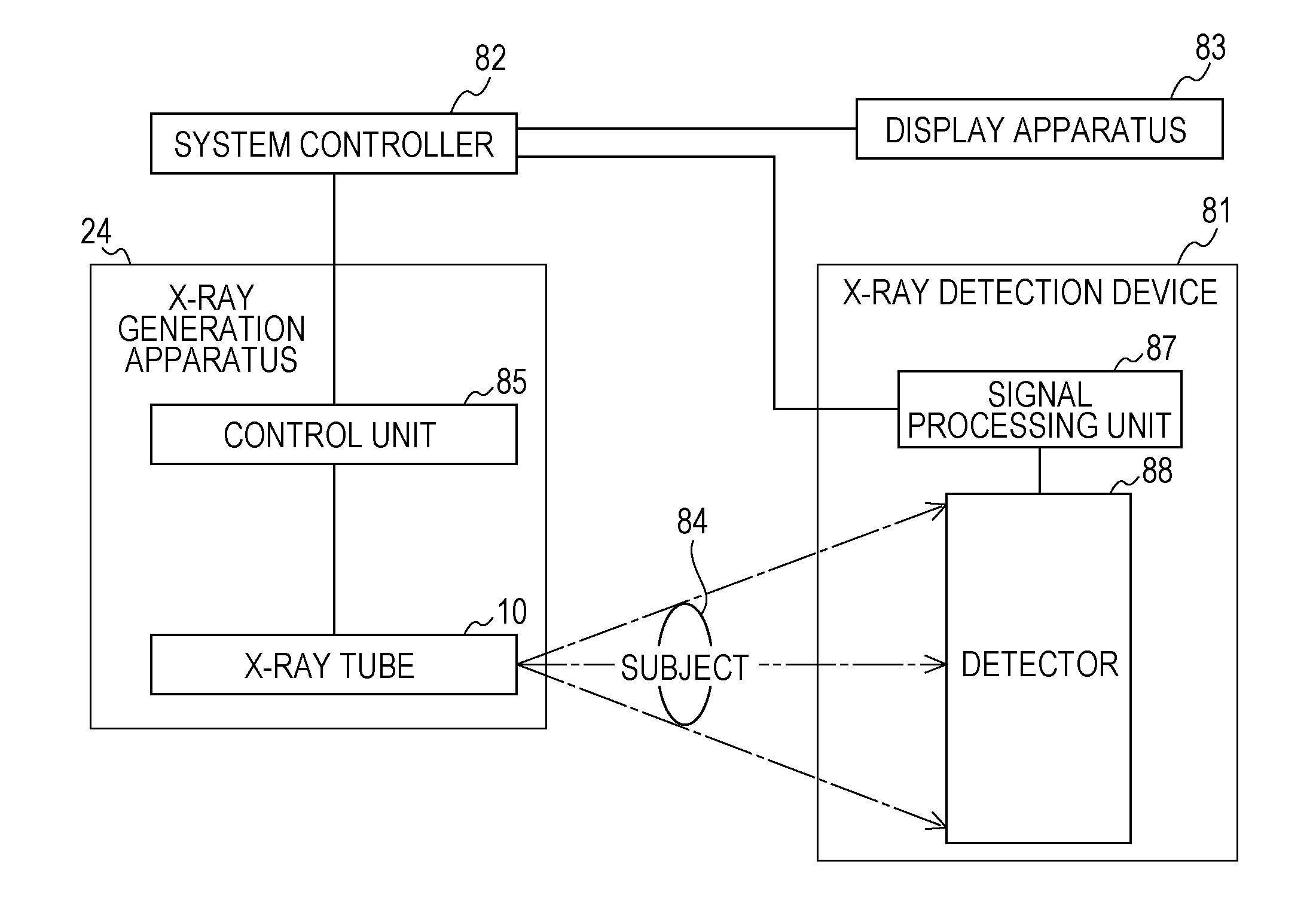
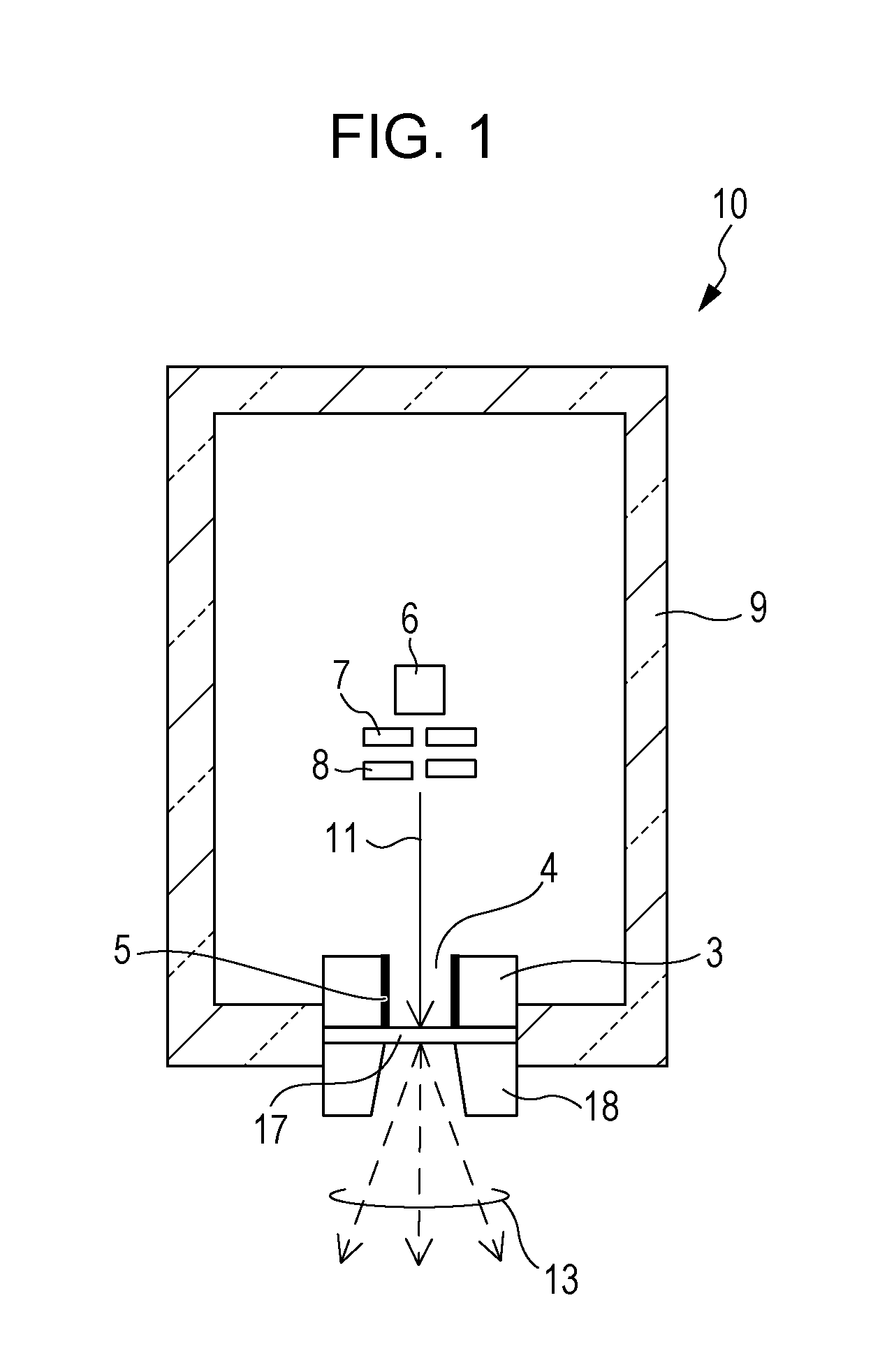
[0018]FIG. 1 is a schematic view of a transmission-type X-ray generation tube (hereinafter referred to simply as an “X-ray tube”) used in the X-ray generation apparatus according to a first embodiment. In the X-ray generation apparatus, an X-ray tube 10 illustrated in FIG. 1 is disposed in an envelope having a window through which an X-ray is taken out, as described later.

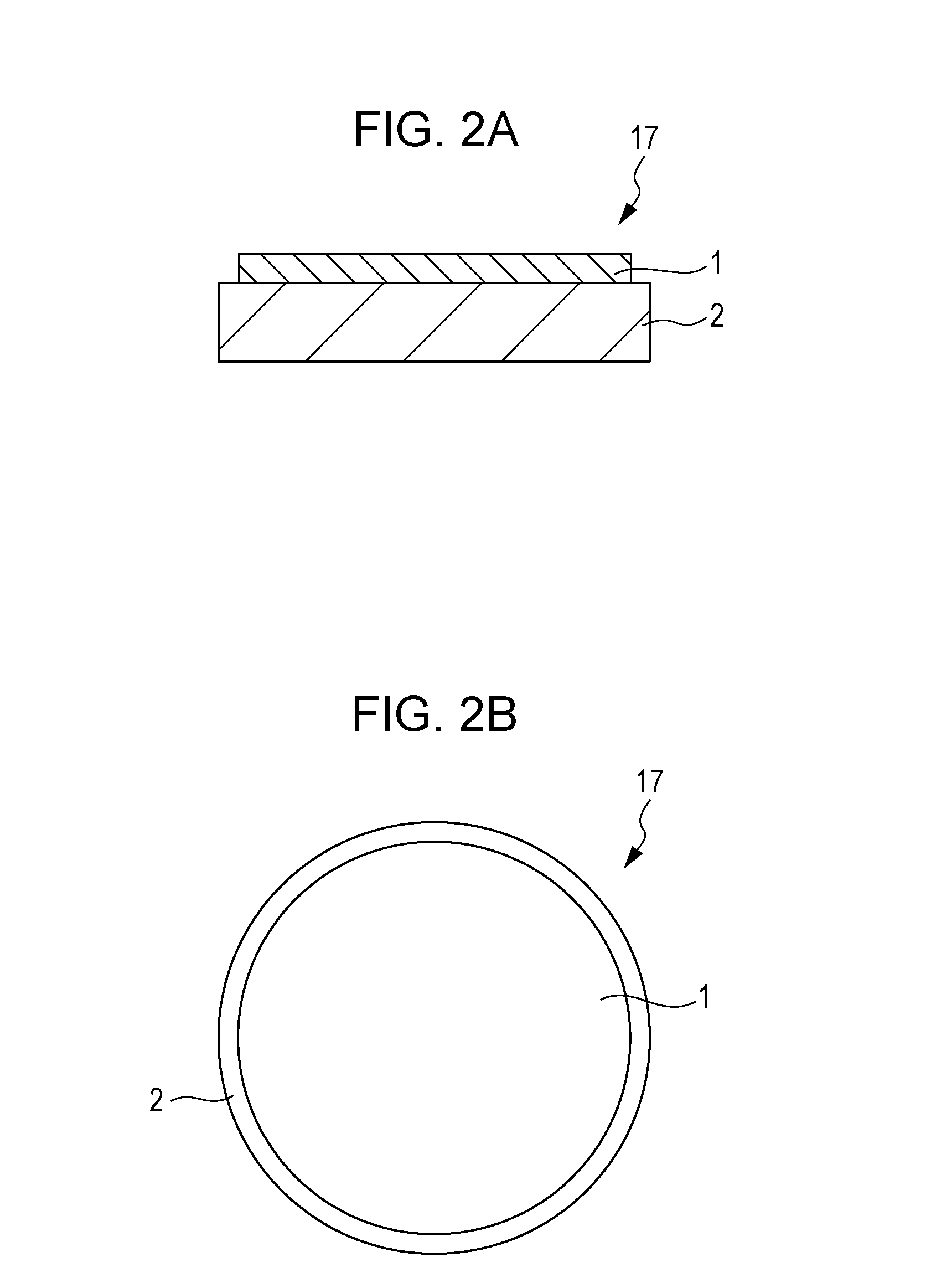
[0019]A vacuum vessel 9 is to keep the inside of the X-ray tube 10 vacuum and is made of, e.g., glass or ceramic materials. A degree of vacuum within the vacuum vessel 9 is kept at about 10−4 to 10−8 Pa. The vacuum vessel 9 has an opening, and an electron passage forming member 3 including an electron passage 4 formed therein is joined to the opening. A target unit 17 is joined to an end surface of the electron passage forming member 3, whereby the vacuum vessel 9 is enclosed. Further, an evacuation pipe (not illustrated) may be mounted to the vacuum vessel 9. When the evacuation pipe is mounted, the inside of the ...

second embodiment

[0043]The structure of an anode 16 used in a second embodiment and an X-ray generation mechanism will be described below with reference to FIG. 4.

[0044]In the anode 16 illustrated in FIG. 4, a cross-sectional area of an electron passage 4 is continuously increased toward the target 1. Further, an inner wall surface of the electron passage 4 in a region where the cross-section area of the electron passage 4 is increased serves as a secondary X-ray generation portion 5. It is just required that at least a part of inner wall surface of the electron passage 4 in the region where the cross-section area of the electron passage 4 is increased serves as the secondary X-ray generation portion 5.

[0045]A suitable range of an angle θ formed by the secondary X-ray generation portion (surface) 5 and the target 1 is discussed below. The secondary X-ray generated from the secondary X-ray generation portion 5 is radiated in all directions. In the case of θ>90°, therefore, a large part of the generat...

third embodiment

[0055]FIG. 6A is a sectional view of an anode 16 used in a third embodiment. FIG. 6B is a plan view of a target unit 17 in FIG. 6A when viewed from the electron incident side. The anode 16 is made up of the target unit 17 (including a support base 2 serving further as an X-ray transmission window, a conductive layer 19, and a target 1), and an electron passage forming member 3 including an electron passage 4. An X-ray generation apparatus according to the third embodiment includes the X-ray tube 10 illustrated in FIG. 1. The third embodiment is featured in arranging the target 1 in a central region of the support base 2 and in using the conductive layer 19. Other points may be similar to those in the first embodiment.

[0056]In the target unit 17, the conductive layer 19 is disposed on the support base 2, and the target 1 is disposed in the central region of the conductive layer 19. In FIGS. 6A and 6B, d1 denotes a diameter of the target 1, and d2 denotes an inner diameter of the elec...


PUM


Abstract

In an X-ray generation apparatus of transmission type including an electron passage surrounded by and formed in an electron passage forming member, and generating an X-ray by colliding electrons having passed through the electron passage against a target, wherein the electron passage includes a secondary X-ray generation portion that generates an X-ray with collision of electrons reflected by the target against the secondary X-ray generation portion, the secondary X-ray generation portion and the target are arranged such that the X-ray generated with direct collision of the electrons against the target and the X-ray generated with the collision of the electrons reflected by the target against the secondary X-ray generation portion are both radiated to an outside, and an atomic number of a material of the electron passage forming member is larger than that of the target. X-ray generation efficiency is increased by effectively utilizing the electrons reflected by the target.

Description

TECHNICAL FIELD[0001]The present invention relates to an X-ray generation apparatus, which can be applied to, e.g., nondestructive X-ray radiography used in the fields of medical equipment and industrial equipment, and also relates to an X-ray radiographic apparatus employing the X-ray generation apparatus.BACKGROUND ART[0002]An X-ray generation apparatus of the type generating an X-ray by colliding (bombarding) electrons against a transmission-type target is suitable for reducing the apparatus size, but X-ray generation efficiency is very low. The reason is that, when electrons are accelerated to a high energy level and are collided against the transmission-type target to generate an X-ray, about 1% or less of energy of the colliding electrons is converted to the X-ray and the rest, i.e., about 99% or more, is converted to heat. Therefore, an improvement of the X-ray generation efficiency is demanded.[0003]PTL 1 discloses an X-ray tube in which the X-ray generation efficiency is in...

Claims


Application Information

Patent Timeline
IPC IPC(8): H01J35/08H01J35/16G01N23/04
CPCH01J35/08G01N23/04H01J2235/081H01J2235/087H01J2235/186H01J35/16H01J2235/168H01J35/116H01J35/186
Inventor OGURA, TAKAOTAMURA, MIKISATO, YASUEHIROKI, TAMAYO
Owner CANON KK
Why Eureka
Try Eureka