Composite fibre component for a rotor blade, device for manufacturing a composite fibre component for a rotor blade and the method for manufacturing a composite fibre component for a rotor blade

Inactive Publication Date: 2014-12-18
SENVION GMBH
View PDF6 Cites 14 Cited by
  • Summary
  • Abstract
  • Description
  • Claims
  • Application Information

AI Technical Summary

Benefits of technology

[0036]If the composite fibre component, in particular at or on the second surface, has a marking for a target position of the further component, an alignment of the composite fibre component and of the further component with respect to each

Problems solved by technology

In this method, the thickness of the component is also only controllable in a relatively inexact manner.
For a rotor blade shell, for example, this means that the aerodynamically significant outside has a surface with an excellent quality, while the inside, onto which t

Method used


Image

  • Composite fibre component for a rotor blade, device for manufacturing a composite fibre component for a rotor blade and the method for manufacturing a composite fibre component for a rotor blade
  • Composite fibre component for a rotor blade, device for manufacturing a composite fibre component for a rotor blade and the method for manufacturing a composite fibre component for a rotor blade
  • Composite fibre component for a rotor blade, device for manufacturing a composite fibre component for a rotor blade and the method for manufacturing a composite fibre component for a rotor blade

Examples


Embodiment Construction

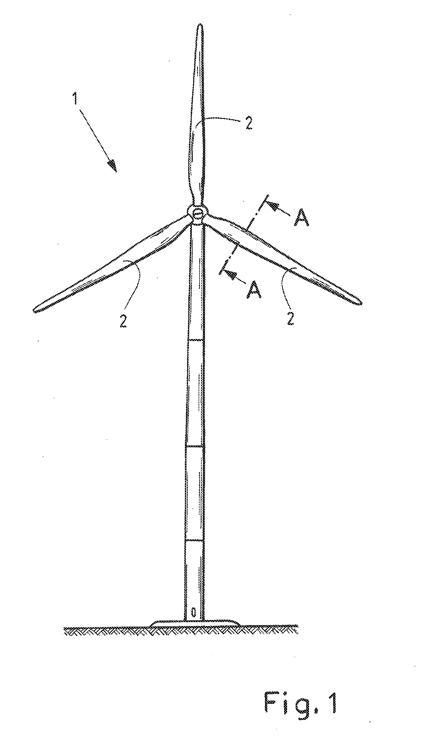
[0046]FIG. 1 shows schematically a typical wind power plant 1 with three rotor blades 2. A rotor blade 2 consists for example of several components produced in a composite fibre construction, which are adhered together.

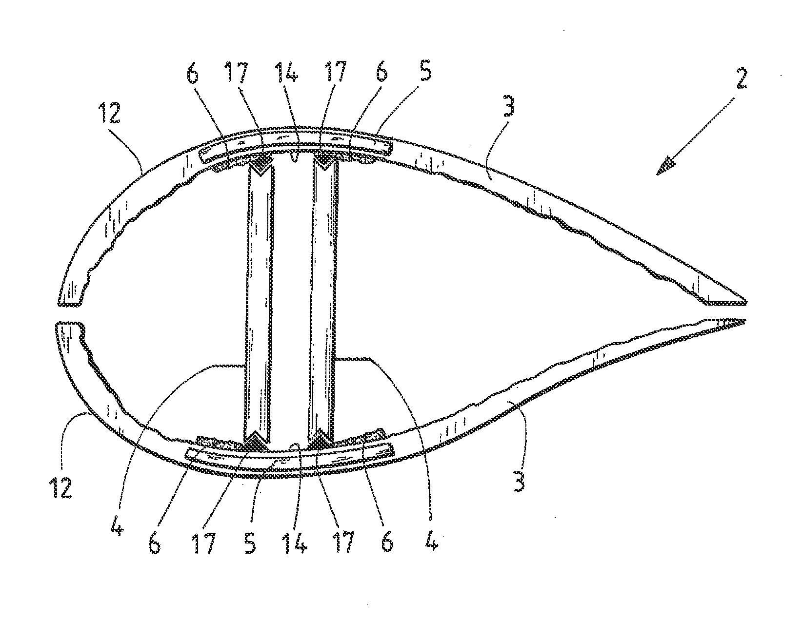
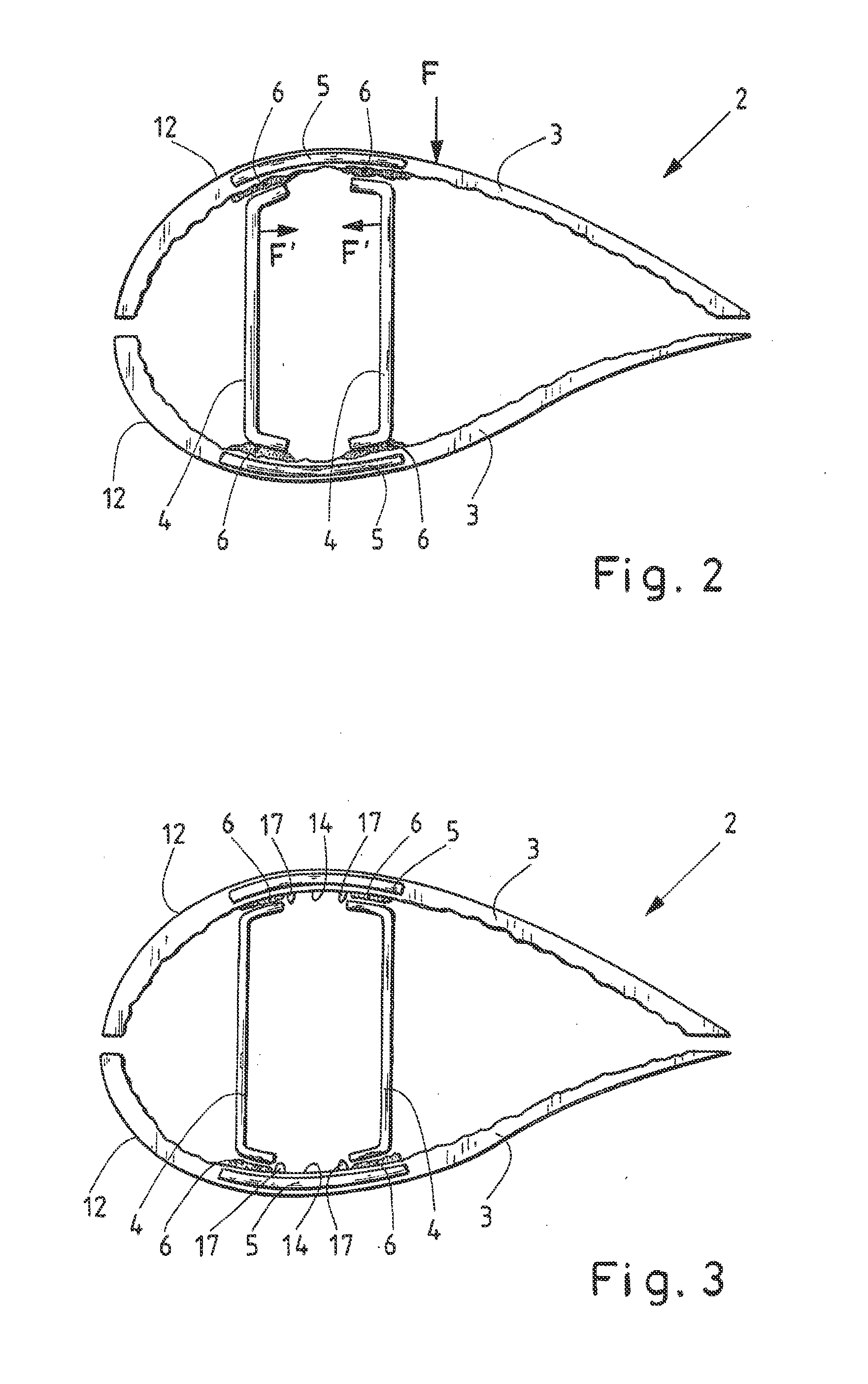
[0047]FIG. 2 shows schematically how a rotor blade 2 from the state of the art is joined together from two rotor blade shells 3 and two r gain webs 4. A sectional representation along the line A-A on the finished rotor blade in FIG. 1 is thereby shown.

[0048]The rotor blade shells 3 as well as the main webs 4 are produced individually in composite fibre construction using a vacuum infusion method. In this process, fibre material is placed in an open manufacturing mould, the manufacturing mould is sealed using a vacuum film, the air located between the manufacturing mould and the vacuum film is evacuated and resin is then directed into the evacuated manufacturing mould so that the fibre material between the manufacturing mould and the vacuum film is saturated with resin...


PUM

PropertyMeasurementUnit
Areaaaaaaaaaaa
Transparencyaaaaaaaaaa

Abstract

A composite fibre component for a rotor blade of a wind power plant having a first surface, shaped in a predefined fashion, on a first side of the composite fibre component. The composite fibre component is developed such that the composite fibre component has a second surface, shaped in a predefined fashion, for connecting to a further component for the rotor blade on at least one partial area of a second side, facing away from the first side, of the composite fibre component. A manufacturing device for manufacturing a composite fibre component for a rotor blade of a wind power plant by using a vacuum infusion method, and to a method for manufacturing a composite fibre component for a rotor blade of a wind power plant by using a vacuum infusion method.

Description

BACKGROUND OF THE INVENTION[0001]1. Field of the Invention[0002]The invention relates to a composite fibre component for a rotor blade of a wind power plant having a first surface, shaped in a predefined fashion, on a first side of the composite fibre component.[0003]Furthermore, the invention relates to a manufacturing device for manufacturing a composite fibre component for a rotor blade of a wind power plant using a vacuum infusion method comprising an open manufacturing mould with a mould surface for moulding a first surface on a first side of the composite fibre component.[0004]Moreover, the invention relates to a method for manufacturing a composite fibre component for a rotor blade of a wind power plant using a vacuum infusion method in an open manufacturing mould, wherein a first surface on a first side of the composite fibre component is or will be moulded by means of a mould surface of the manufacturing mould.[0005]The invention further relates to a rotor blade for a wind ...

Claims


Application Information

Patent Timeline
IPC IPC(8): F03D1/06B29C70/54B29C70/68B29C70/48
CPCF03D1/0675B29C70/48B29C70/54B29C70/68B29K2105/25B29K2823/06B29K2995/0026B29L2031/08B29C70/681F05B2280/6003Y02E10/72Y02P70/50
Inventor FLACH, CHRISTIAN
Owner SENVION GMBH
Why Eureka
Try Eureka