Methods, processing device, computer programs, computer program products, and antenna apparatus for calibration of antenna apparatus

Inactive Publication Date: 2014-12-18
OPTIS CELLULAR TECH LLC
View PDF31 Cites 21 Cited by
  • Summary
  • Abstract
  • Description
  • Claims
  • Application Information

AI Technical Summary

Benefits of technology

The patent describes a method to calibrate antennas in real-time and without interrupting normal service. The method improves accuracy and reduces calculation complexity. It achieves simultaneous calibration for a wideband system and detects jointly the group delays for all sub-bands. It also reduces hardware components and improves calibration performance. The method requires less processor load and can be finished in one half-frame for transmit and receive calibration, respectively.

Problems solved by technology

Since the antenna's transceiver apparatus chains always consist of different Intermediate Frequency (IF) and RF process elements, they often experience different amplitude degradation and phase shift.
Further, the antenna elements, feeder cable and RF circuitry composed of analog electronic components also often suffer from different amplitude attenuation and phase shift with temperature, humidity and device aging.
This makes it more difficult to ensure that the overall channel response of the RF chains of the eNodeB are close to ideal and thus introduces significant variations over frequency of the effective channel over the entire bandwidth.
If not properly dealt with it, the system may have to cope with a substantial increase of frequency-selectivity, which may have serious implications on channel estimation quality as well as the performance of beam-forming or pre-coding.
However, the amplitude and phase difference among the antennas apparatus chains cannot be detected easily.
However, such solution is hard to implement in a wideband system.
However, in such solution, the estimation accuracy is highly limited.
In field tests, the error of beam-forming pattern is often limited to less than 5 degrees by telecommunication operator.
All the above antenna calibration approaches often fail to the strict calibration accuracy and complexity on the phase and amplitude of the array antennas, particularly if applied to wideband systems.

Method used


Image

  • Methods, processing device, computer programs, computer program products, and antenna apparatus for calibration of antenna apparatus
  • Methods, processing device, computer programs, computer program products, and antenna apparatus for calibration of antenna apparatus
  • Methods, processing device, computer programs, computer program products, and antenna apparatus for calibration of antenna apparatus

Examples


Embodiment Construction

[0026]In the following description, for purposes of explanation and not limitation, specific details are set forth such as particular architectures, interfaces, techniques, etc. in order to provide a thorough understanding. In other instances, detailed descriptions of well-known devices, circuits, and methods are omitted so as not to obscure the description with unnecessary detail. Same reference numerals refer to same or similar elements throughout the description.

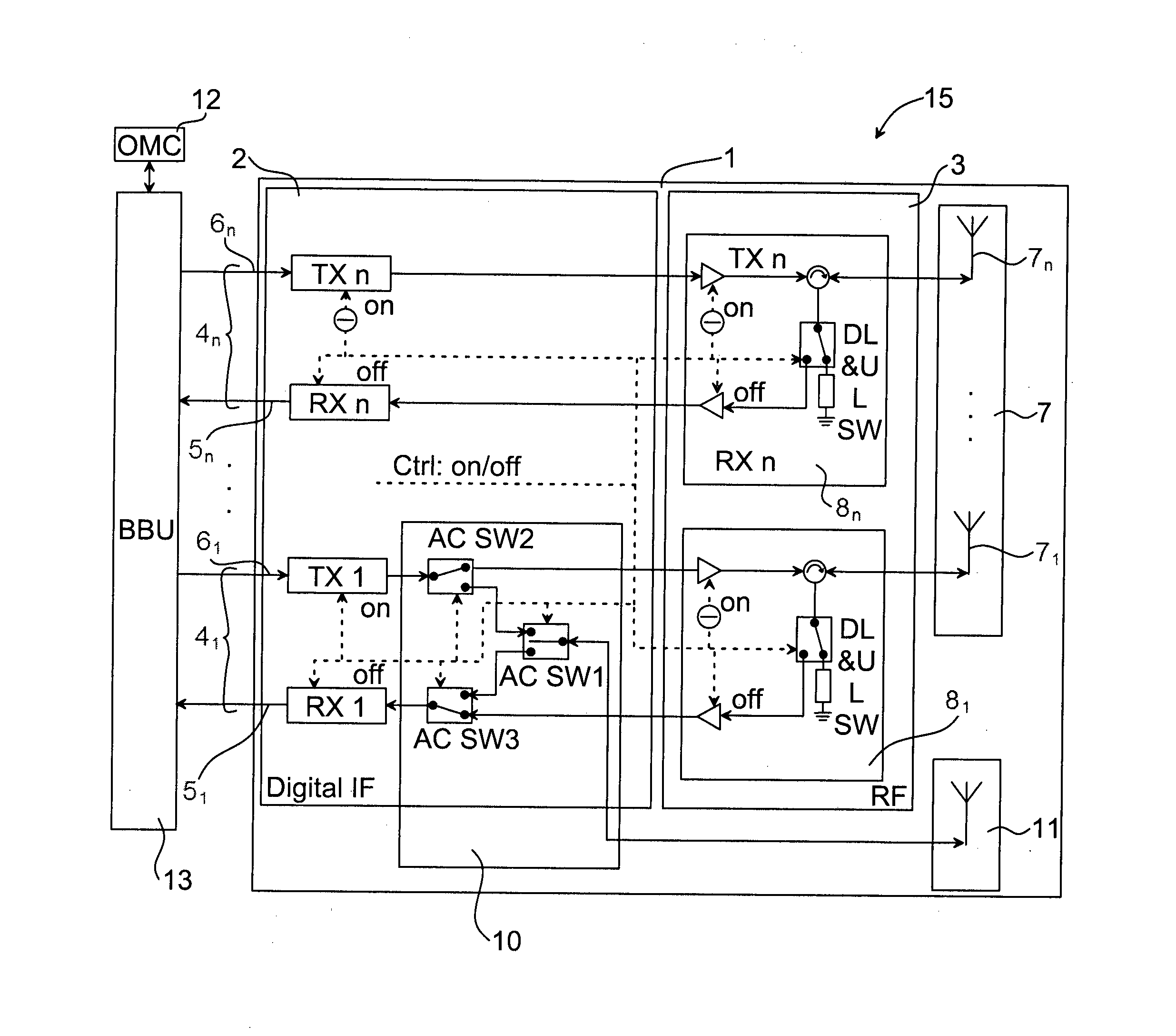
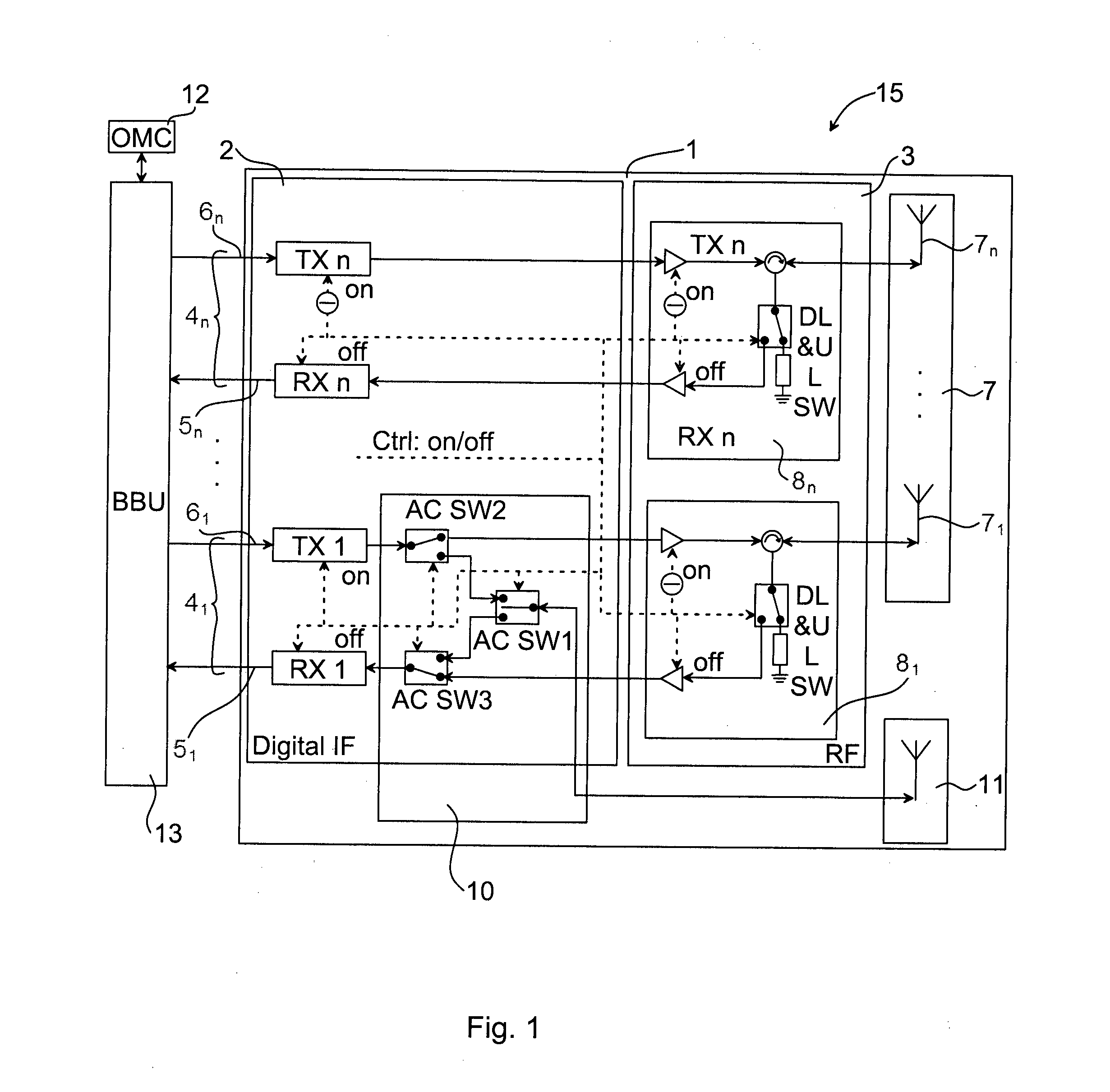
[0027]FIG. 1 illustrates an antenna array system 15 comprising an antenna apparatus 1 in accordance with an embodiment. The antenna apparatus 1 may for example comprise a remote radio unit (RRU) 1.

[0028]The antenna apparatus 1 comprises a transceiver part 2 and a power amplifier part 3 (or radio frequency part). The power amplifier part 3 comprises for each of a number of transceiver chains 41, . . . , 4n transmit / receive switches 81, . . . , 8n for switching a transmit chain 6i or a receive chain 5i to an antenna element...


PUM


Abstract

The invention relates to a method 20 in an antenna array system 15 for calibration of an antenna apparatus 1. The method 20 comprises: estimating 21 coarse receive delays for the receive chains 51, . . . , 5n and coarse transmit delays for the transmit chains 61, . . . , 6n; adjusting 22 a timing of the receive chains 51, . . . , 5n based on the estimated coarse receive delays so that the receive chains 51, . . . , 5n align with the maximum coarse receive delay difference and adjusting a timing of the transmit chains 61, . . . , 6n based on the estimated coarse transmit delays so that the transmit chains 61, . . . , 6n align with the maximum coarse transmit delay difference; estimating 23 a fine delay and initial phase for the receive chains 51, . . . , 5n and the transmit chains 61, . . . , 6n based on their phase-frequency characteristics; adjusting 24 an intermediate frequency timing of the antenna apparatus 1 based on the estimated fine delay; compensating 25 initial phase and residual delay at base band frequency-domain signal; estimating 26 amplitude-frequency characteristics of the transceiver chains 41, . . . , 4n; and compensating 27 the estimated amplitude-frequency characteristics at base band frequency-domain signal.

Description

TECHNICAL FIELD[0001]The technology disclosed herein relates generally to the field of antenna technology of wireless communication systems, and in particular to antenna calibration within such communication systems.BACKGROUND OF THE INVENTION[0002]Multiple antennas technology is widely adopted in wireless communication for providing higher data rates and larger coverage, e.g. in Time Division Synchronous Code Division Multiple Access (TD-SCDMA), Time Division Long Term Evolution (TD-LTE) and near future LTE-advanced system. In multiple antennas array, a plurality of antennas are spatially arranged and their respective transceivers are electrically connected via a feed network so as to cooperatively transmit and / or receive Radio Frequency (RF) signals using beam-forming or pre-coding techniques. The adaptive beam-forming is able to automatically optimize the radiation beam pattern of the antennas array to achieve high gain and controlled beam-width in desired directions by adjusting...

Claims


Application Information

Patent Timeline
IPC IPC(8): H04B1/40H04B17/00
CPCH04B1/401H04B17/0007H04B17/0062H04B7/04H04B17/12H04B17/21H04B17/14
Inventor YU, SHAOWEI
Owner OPTIS CELLULAR TECH LLC
Why Eureka
Try Eureka