
Guardrail stanchion and system

Active Publication Date: 2014-12-25
OUICANDUIT
View PDF2 Cites 9 Cited by
  • Summary
  • Abstract
  • Description
  • Claims
  • Application Information

AI Technical Summary

Benefits of technology

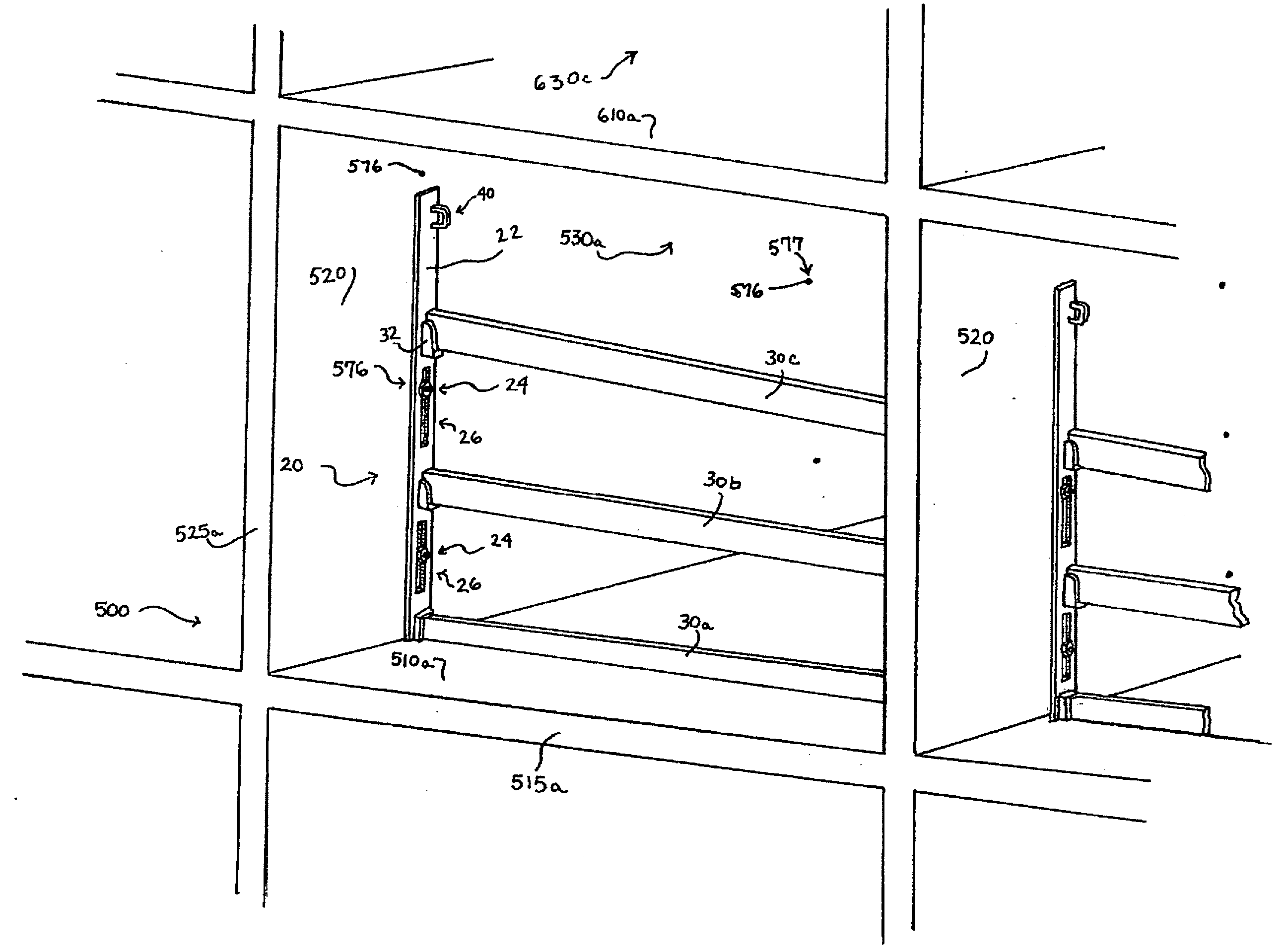
This patent describes a way to secure a guardrail device to the edge of a deck or other opening of a structure without damaging the structure or having to remove the guardrails to work on or about the edge of the slab. This system can also be used as a life-line anchorage, which reduces risks and is less expensive than traditional anchorage mechanisms. By utilizing a through-hole in a concrete wall, a guardrail stanchion can be securely affixed to the wall within the bay without needing to damage the deck. This system reduces labor costs and overall costs of construction, while also improving safety standards and efficiency in set-up and maintenance.

Problems solved by technology

Connecting devices to the floor of a structure, such as by nailing a standard or stanchion to a concrete floor results in damage to the floor, often requiring expensive or time-consuming repair, among other problems.
While such mechanisms generally avoid direct damage to the floor or structure, and also avoid placement or coverage over the edge of the slab, the reliability of such compression-fit mechanisms is questioned.
Natural or unnatural changes, such as expansion or contraction of the structure materials, present concern due to slippage of the devices from a secured safety position within the bay of the structure.
Such differences in the material characteristics of the device and structure present further variability issues for the stability of a compression-fit system.
The changed forces may cause the device to break, or to slip or weaken its fit against the structure, or if the device does not yield, in an extreme case the structure may shift or crack.
In either case, the expansion of the device might lift the ceiling slightly, thereby causing other posts or shoring devices to loose their compression fit.
In some cases the posts fall from position and are otherwise unworkable as a safety device.
In sum, the compression-fit devices having a post span from floor to ceiling are inherently suspect and unworkable for use in a safety role.
By the same token, compression-fit posts that span from wall-to-wall are also unworkable.
In practice it was found that the wedging of such vertical pieces of lumber can never be made completely secure and the lumber will rapidly dry out, being exposed to very severe weathering, and will become loose and sometimes blow away altogether causing an additional hazard to persons standing below.
The same thing can occur merely because the concrete itself dries out and will shrink very slightly thereby causing such vertical pieces of lumber to become loose and fall (or in other cases, cause the lumber to tighten or result in bowing or nail pulls).
The appearance of the otherwise safe structure may cause a false sense of security, further exacerbating the hazard.
However, such systems lack the simplicity and reliability of the present invention.
They also are subject to variables encountered with material expansion as noted above, and thus are suspect and unreliable for a safety role.
Other drawbacks of such friction-fit mechanisms include the cost of having columns span from floor-to-ceiling or having expensive threaded components or other means for telescoping action.
The size of the floor-to ceiling mechanisms are bulky and often troublesome to transport and / or store.
Further, the over-tightening of a post or column may result in damage to the floor or ceiling and corresponding loosening of adjacent posts or columns.
Such mechanisms are generally troublesome to set-up.
Disadvantageously, while the above and other past approaches may be sufficient in some respects for their particular purposes, each has deficiencies.
Some of the approaches require a considerable effort in set-up and take-down; or still result in damage to the structure (such as by nailing, which commonly requires drilling or use of a hammerdrill or other aggressive tools) which in turn requires additional expense, delay and labor for correction; or connect adjacent to, or cover up, the edge of the structure thus requiring subsequent movement in order to work on or at the edge location; or rely on a compression or friction fit which is susceptible to slippage and other troubles as mentioned.
Further, with such approaches there is an ever-present uncertainty as to whether the systems are indeed compliant with OSHA or other requirements, or if initially compliant, whether they can maintain compliance and be safe throughout the construction effort.
Even if some of the prior systems comprise a “standard railing” and / or guardrail system that securely connects to the structure without nailing or other damage to the structure, they are either of a compression-fit variety, or disadvantageously cover the edge location of the flooring.
The known guardrail devices are often complicated, expensive, typically result in damage to the structure to which they are affixed, are difficult to secure, and are susceptible to non-compliance with OSHA.
Many are not reusable, many are limited to a particular site configuration, require temporary removal and re-setting when a forklift needs access, are in the way when working on an outside edge of the structure (such as when laying brick or pouring outside edge wall or constructing outside edge wall), require the subsequent patching of holes or damage to the structure or require rework of concrete that was damaged by a nail gun or drill or other anchor mechanism.
Damages made to the walls of a structure have become increasingly problematic in recent years especially since owners of the structures sometimes prefer to keep the raw walls exposed to view for aesthetic purposes.
Drilling into the floor or walls or ceilings creates unsightly marks, and the repairs are often unsatisfactory.
Thus, drilling into the walls becomes risky.
Indeed, safety mechanisms are required to be used on a project, so the workers and owners often have to deal with the competing goals of safety vs. appearance and costs.
Traditional guardrail mechanisms have not been secure enough to accommodate such use.
Thus, traditional floor-to-ceiling or shoring mechanisms might not be acceptable for use as a life-line anchorage.
The mere presence of unstable yet seemingly safe shoring mechanisms may result in an unfortunate instance of a worker unwittingly or improperly using such systems for life-line purposes.
Removal of the ties results in a through-hole in the wall.

Method used


Image

  • Guardrail stanchion and system
  • Guardrail stanchion and system
  • Guardrail stanchion and system

Examples


Embodiment Construction

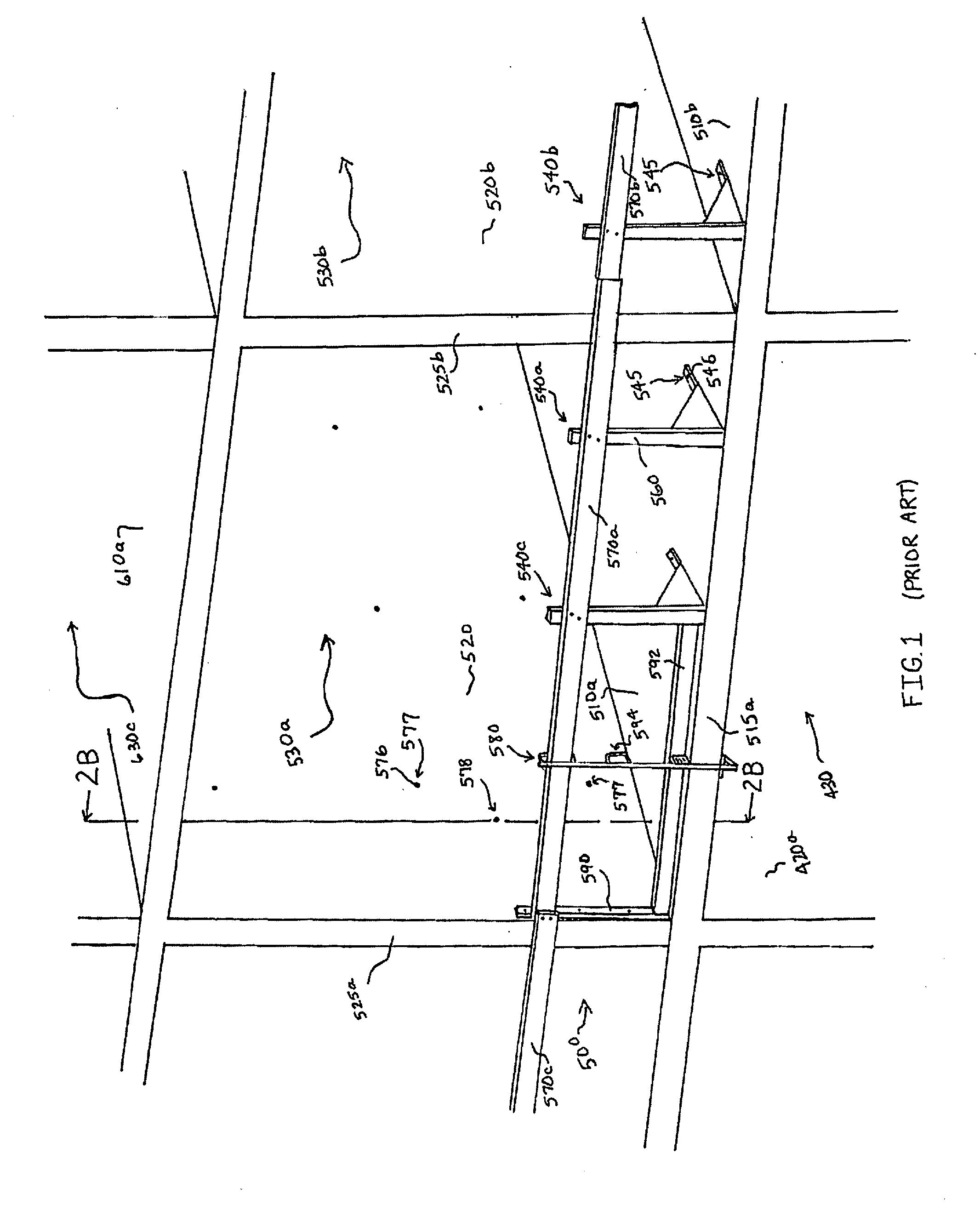
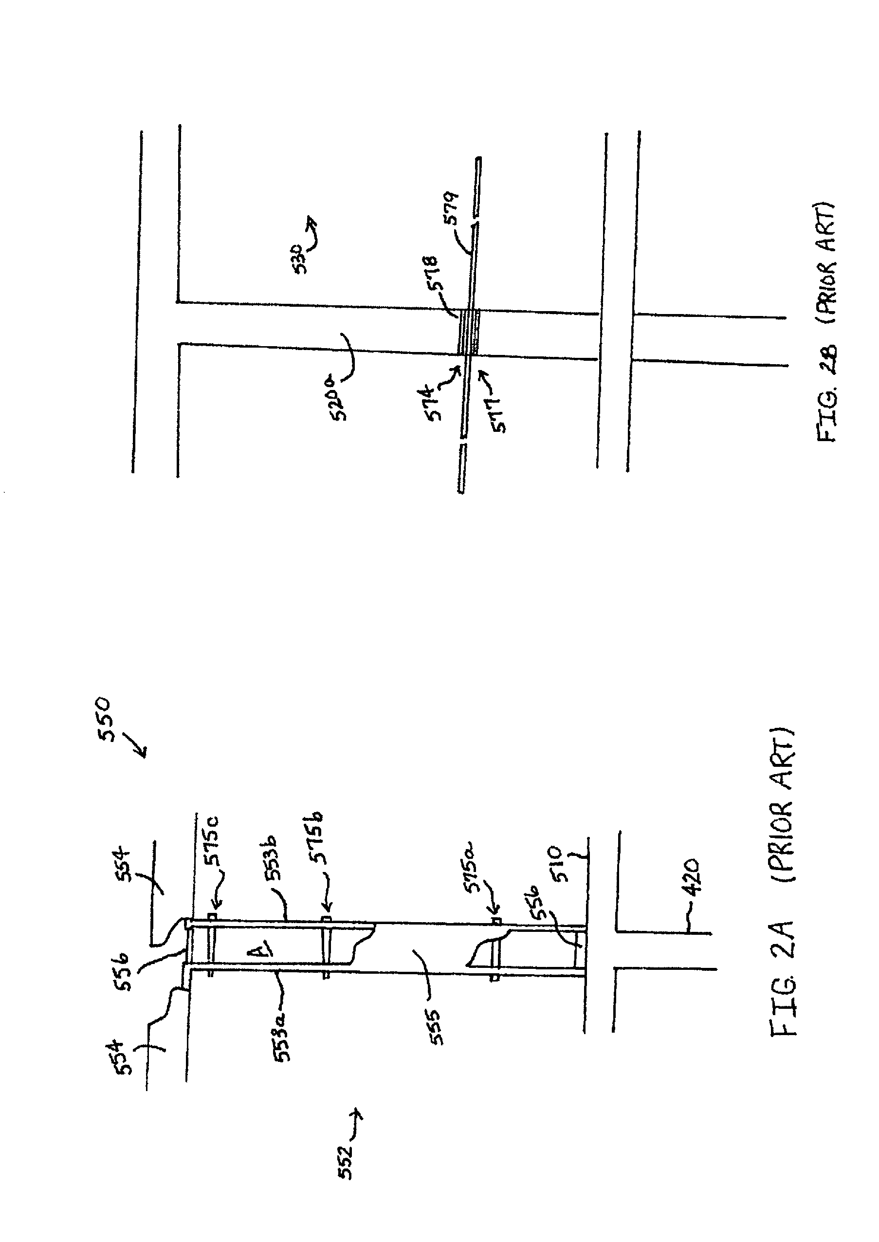
[0046]Among the guardrail systems known in the prior art are those referenced in the background section, above, as well as the example as shown in FIG. 1. FIG. 1 shows a prior art example of a guardrail system positioned upon a multi-story building. Supports 540a, 540b, 540c are secured to the floor or slab 510 (for instance, at slab 510a, 510b, or the like) of a concrete structure 500 under construction. Structure 500 typically includes concrete slabs or floors 510 and concrete walls 520 (for instance, walls 520a, 520b, or the like) which are reinforced with steel cables, re-bar, mesh (combinations thereof) or other reinforcements. Structure 500 may accommodate a high-rise apartment or office building or other structure. A number of bays 530, such as bay 530a, 530b, 530c or the like are created which comprise various rooms of the building under construction. For instance, bays 530 may be the beginnings of the rooms to be constructed on the fifth floor (or alternatively some other f...


PUM


Abstract

A guardrail system (20) and method comprises utilizing at least one through-hole (577) of a poured concrete wall (520) of a structure (500) to affix a stanchion (22, 122, 222) to the wall inside a bay (530) of the structure. The stanchion allows for a guardrail (30) or a gate to be conveniently and securely positioned within the bay (530) without damage to the structure and without covering an edge (515, 525) of the structure (500). A fastener (24) inserts through the through-hole (577) which is a pre-existing tie-hole (576) resulting from formation of the wall (520). In one optional aspect a guardrail stanchion (222) includes a base segment (50) having at least two slots (26) for receiving fasteners (24) which insert through two tie-holes (576) of the wall (520), and at least one side segment (52) having at least one adjustment port (56), the side segment (52) extending generally perpendicular to the base segment (50). A pair of stanchions (22, 122, 222) may be affixed to opposing walls within the bay, and guardrails (30) affixed thereto and spanning across the bay (530). The system (20) may also include a cable system (80) having a cable (579) operate as a guardrail (30) to be tightened by utilizing a stanchion (22, 122, 222) in accordance with the invention. Additional aspects are also presented for utilizing timber stanchions (22, 122, 222) and nylon straps (30), among other aspects.

Description

BACKGROUND[0001]1. Field of the Invention[0002]The present invention relates generally to guardrail stanchions, guardrail systems and methods of affixing stanchions, and more specifically to stanchions, guardrail systems and methods for use on construction sites, and particularly to stanchions, guardrail systems and methods for use on concrete structures.[0003]2. Background Information[0004]Several guardrail devices are known that allow for safety protection at the edge of a construction, such as guardrails placed to prevent workers or objects from falling off the edge of a building under construction. Some form of protective barrier or guardrail is usually required around the edges of the workplace. Detailed regulations are established by various bodies designed to eliminate or reduce workplace hazards. Organizations such as the Occupational Safety and Health Administration (OSHA) in the United States and various state agencies, Workmen's Compensation Boards and trade organizations...

Claims


Application Information

Patent Timeline
IPC IPC(8): E04G21/32
CPCE04G21/3219Y10T29/49623
Inventor CANDLER, LEWISWIEDENBECK, WESLEYBOURGET, ANTHONY
Owner OUICANDUIT
Learn More