Vehicle air conditioning apparatus
a vehicle air conditioning and apparatus technology, applied in the direction of domestic cooling apparatus, defrosting, etc., can solve the problems of difficulty in acquiring exhaust heat that can heat the air by using an electric motor without an engine, and the above-mentioned vehicle air conditioning apparatus is not applicable to electric cars, so as to improve the efficiency of air conditioning operation, reduce pressure loss, and improve the effect of air conditioning operation
- Summary
- Abstract
- Description
- Claims
- Application Information
AI Technical Summary
Benefits of technology
Problems solved by technology
Method used
Image
Examples
embodiment 1
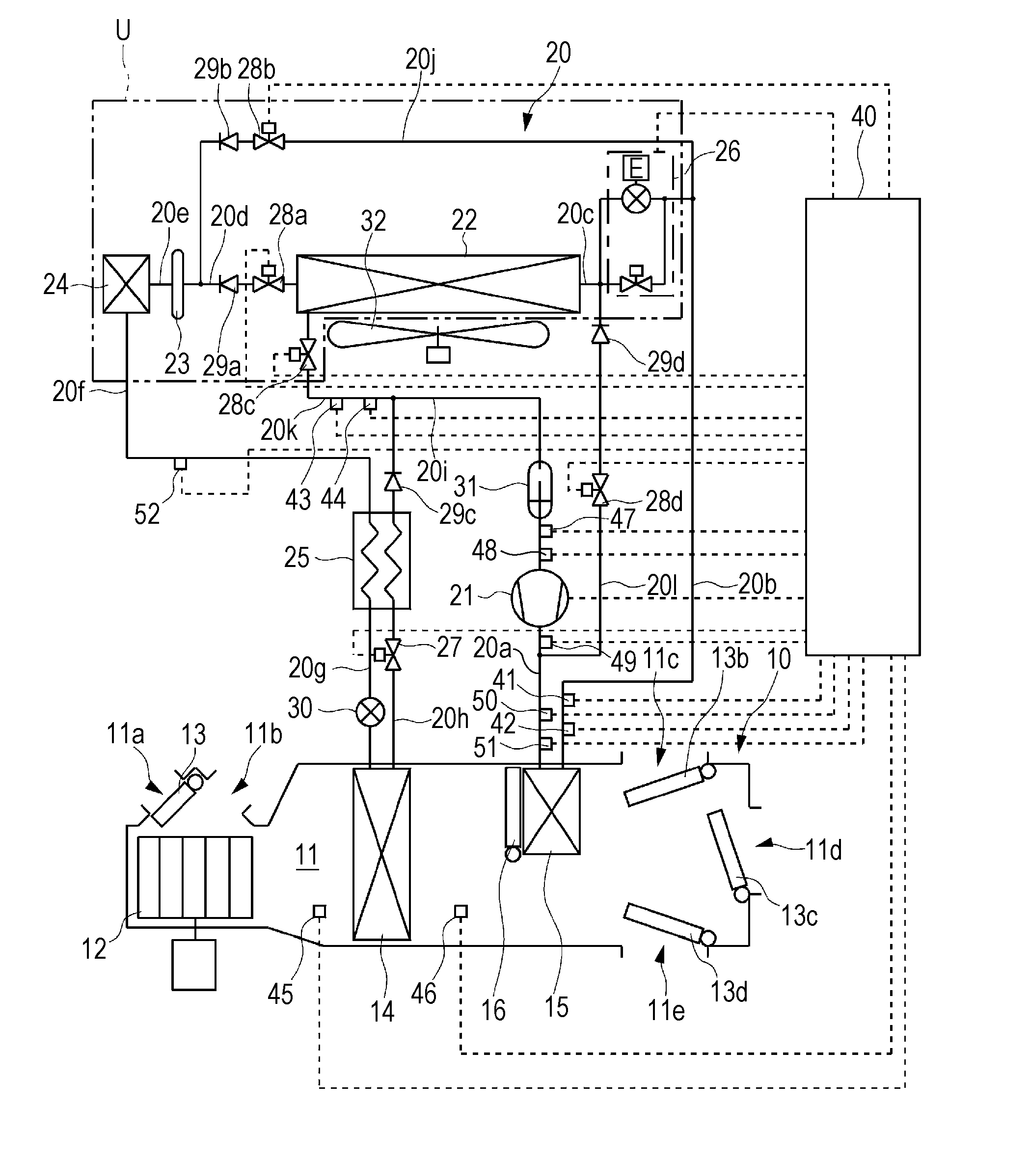
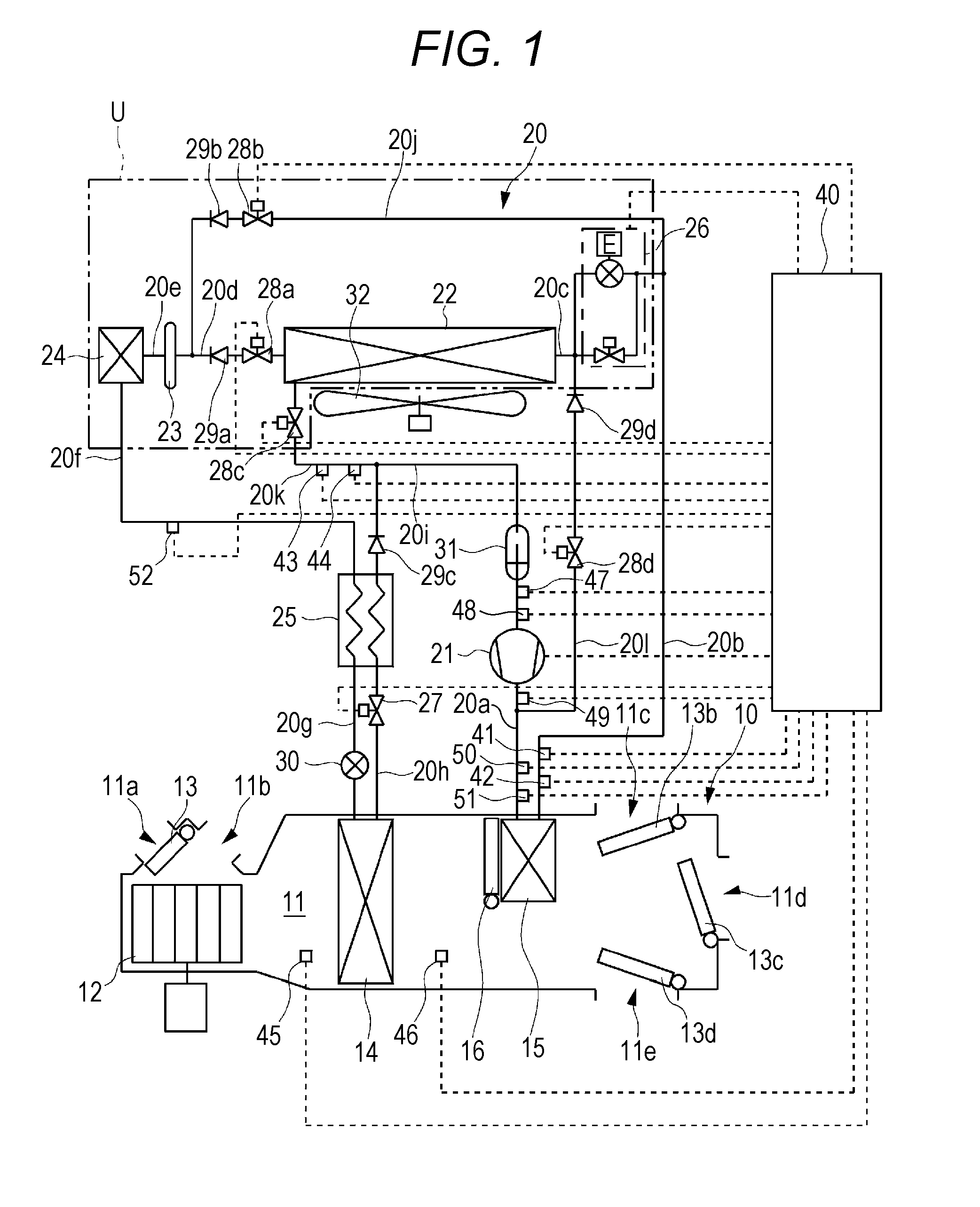
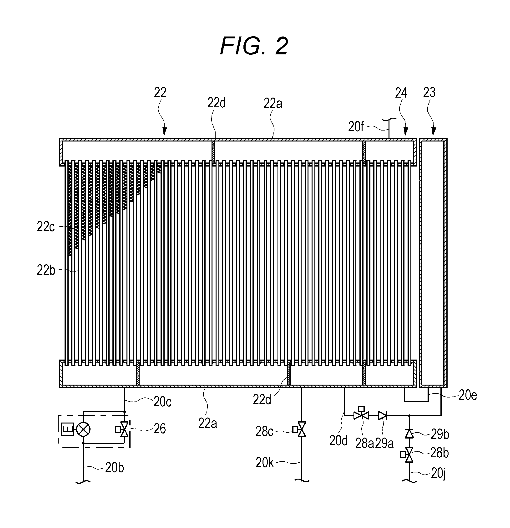
[0047]FIG. 1 to FIG. 12 show Embodiment 1 of the present invention.
[0048]As shown in FIG. 1, the vehicle air conditioning apparatus according to the present invention includes an air conditioning unit 10 provided in the vehicle interior, and a refrigerant circuit 20 formed across the vehicle interior and the outdoor.
[0049]The air conditioning unit 10 includes an air flow passage 11 that allows the air to be supplied to the vehicle interior to pass through. An outdoor air inlet 11a and an indoor air inlet 11b are provided in the first end side of the air flow passage 11. The outdoor air inlet 11a is configured to allow the outdoor air to flow into the air flow passage 11, and the indoor air inlet 11b is configured to allow the indoor air to flow into the air flow passage 11. Meanwhile, a foot outlet 11c, a vent outlet 11d and a defroster outlet 11e are provided in the second end side of the air flow passage 11. The foot outlet 11c is configured to allow the air flowing through the ai...
embodiment 2
[0144]FIGS. 13 and 14 show Embodiment 2 of the present invention. Here, the same components are assigned the same reference numerals as in the above-described embodiment.
[0145]As shown in FIG. 13, the refrigerant flow passage 20e is connected to the refrigerant flow passage 20f, thereby to form a refrigerant flow passage 20m in the refrigerant circuit 20 of the vehicle air conditioning apparatus. A fifth solenoid valve 28e is provided in the refrigerant flow passage 20m. In addition, a sixth solenoid valve 28f is provided downstream from the connection part of the refrigerant flow passage 20e with the refrigerant flow passage 20m. Moreover, a fifth check valve 29e is provided in the upstream side of the connection part of the refrigerant flow passage 20f with the refrigerant flow passage 20m.
[0146]In the vehicle air conditioning apparatus having the above-described configuration, the opening and closing of each of the first control valve 26, the second control valve 27, the first t...
embodiment 3
[0150]FIGS. 15 and 16 show Embodiment 3 of the present invention. Here, the same components are assigned the same reference numerals as in the above-described embodiment.
[0151]As shown in FIG. 15, the refrigerant flow passage 20m and the third check valve 29c are provided in the refrigerant circuit 20 of the vehicle air conditioning apparatus, like Embodiment 2. A three-way solenoid valve 28g is provided at the connection point between the refrigerant flow passage 20e and the refrigerant flow passage 20m.
[0152]In the vehicle air conditioning apparatus having the above-described configuration, the opening and closing of each of the first control valve 26, the second control valve 27, the first to forth solenoid valves 28a, 28b, 28c and 28d, and the three-way solenoid valve 28g is switched during the cooling operation, the cooling and dehumidifying operation, the heating operation, the first heating and dehumidifying operation, the second heating and dehumidifying operation and the d...
PUM
 Abstract
Description
Claims
Application Information
 - R&D
- Intellectual Property
- Life Sciences
- Materials
- Tech Scout
- Unparalleled Data Quality
- Higher Quality Content
- 60% Fewer Hallucinations
Browse by: Latest US Patents, China's latest patents, Technical Efficacy Thesaurus, Application Domain, Technology Topic, Popular Technical Reports.
© 2025 PatSnap. All rights reserved.Legal|Privacy policy|Modern Slavery Act Transparency Statement|Sitemap|About US| Contact US: help@patsnap.com


