Breathing Apparatus

Active Publication Date: 2014-12-25
CLEANSPACE IP PTY LTD
View PDF9 Cites 38 Cited by
  • Summary
  • Abstract
  • Description
  • Claims
  • Application Information

AI Technical Summary

Benefits of technology

[0034]In an embodiment, the breathing apparatus comprises a bypass arrangement, which is arranged to enable airflow to bypass the airflow generator in a non-powered mode of the breathing apparatus. This has the advantage of reducing resistance to airflo

Problems solved by technology

Such environments include polluted industrial areas, hospitals and other potentially hazardous environments.
Conventional

Method used


Image

  • Breathing Apparatus
  • Breathing Apparatus
  • Breathing Apparatus

Examples


Embodiment Construction

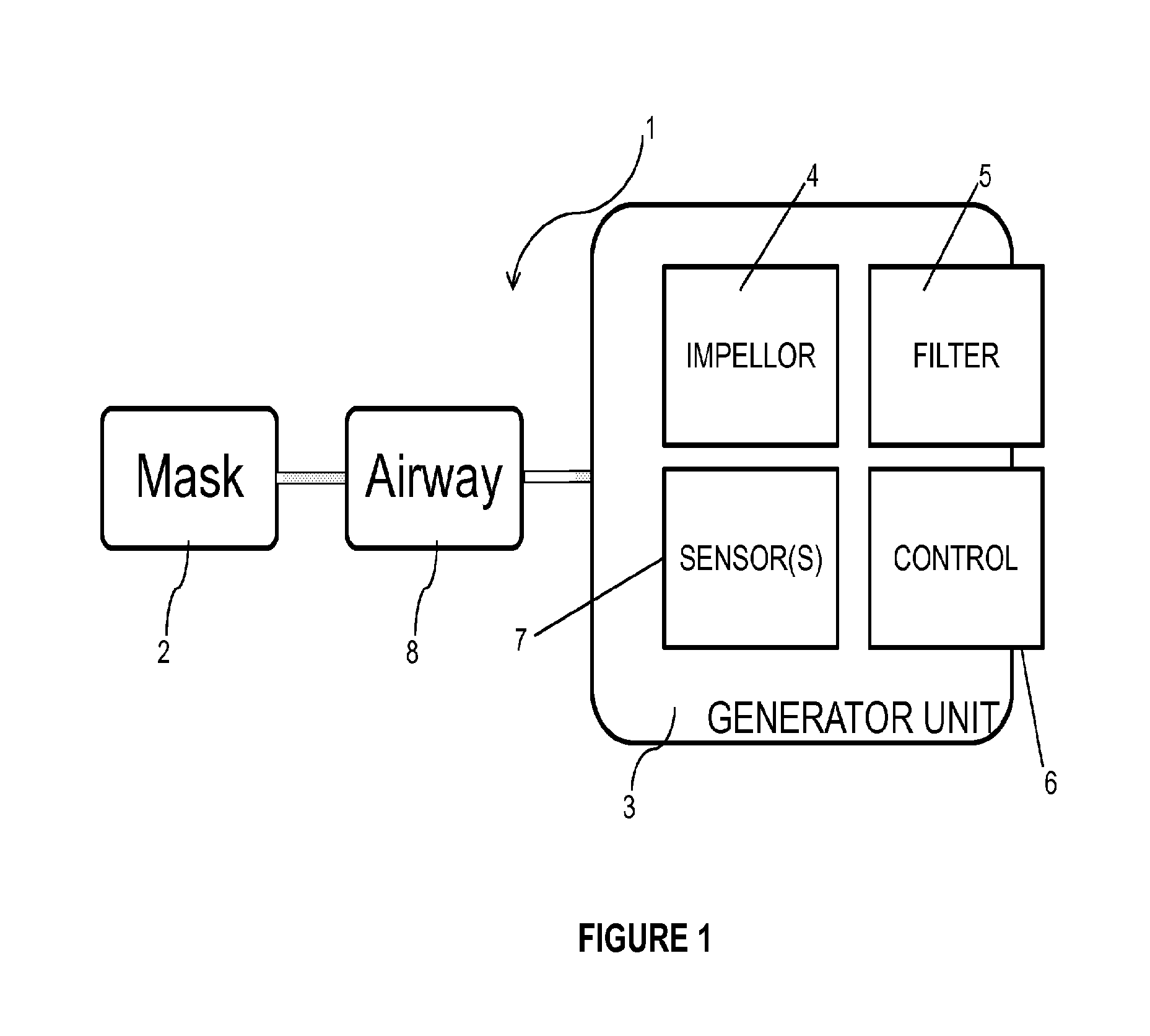
[0118]FIG. 1 is a block diagram showing components of a powered air purifying respirator (PAPR) system, in accordance with embodiments of the present invention. The PAPR system 1 comprises the following components:

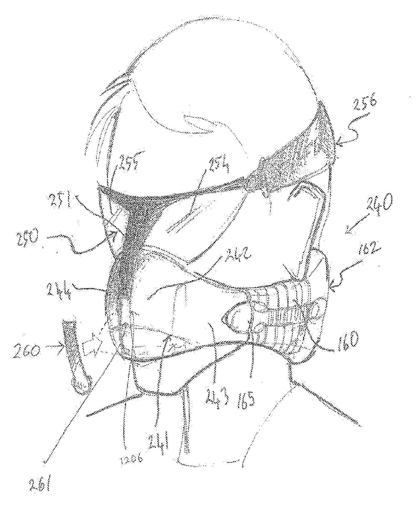
[0119](a) a mask 2, which, in use, is arranged to form a closed chamber about the mouth and / or nose orifices of a user. The chamber formed by the mask is arranged to receive purified air which, in this example, is under positive pressure;

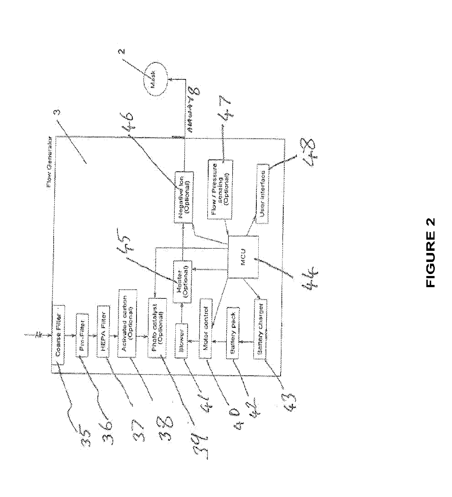
[0120](b) an air flow generator and filter unit 3 (generator unit). In this example, the air flow generator comprises an impeller 4 with power supply (not shown) which is arranged to positively pressurise air drawn in from the outside environment. The generator unit 3 also comprises a filter 5 arranged to filter the air, a control unit 6 for controlling the generator unit 3, and, in some embodiments, one or more sensors for sensing air pressure / air quality.

[0121](c) An airway 8 which is arranged to convey positively pressurised air from th...


PUM


Abstract

The present invention relates to improvements to powered air purifying respirators (PAPR). PAPR are known generally for use in polluted environments. A typical PAPR comprises a powered impellor arranged to draw air from the atmosphere, a filter element and a mask to provide the filtered and pressurized air to the user. Embodiments of the present invention place a generator unit, comprising a filter and impellor for pressurizing the air, behind the head of the user, and include components for improving delivery of the air to the user and improving its quality.

Description

FIELD OF THE INVENTION[0001]The present invention relates to improved breathing apparatus and, particularly, but not exclusively to improvements to powered air purifying respirators.BACKGROUND OF THE INVENTION[0002]Breathing apparatus such as powered air purifying respirators (PAPR) are known generally, for use in polluted environments. A typical PAPR comprises a powered impeller arranged to draw air from the atmosphere and a filter element through which the air is passed. The impeller positively pressurises the air and transfers it to a users airways via a mask. PAPR devices are used where the environment is heavily polluted or hazardous. Such environments include polluted industrial areas, hospitals and other potentially hazardous environments.[0003]Conventional PAPRs tend to be bulky, awkward, and uncomfortable to wear. This is a disincentive to their use. Typical PAPRs are difficult to wear and use for long periods.[0004]The present Applicants have designed a low profile “PAPR” ...

Claims


Application Information

Patent Timeline
IPC IPC(8): A62B7/10A61F9/02
CPCA61F9/02A62B7/10A62B18/02A62B18/006
Inventor KAO, DANVIRR, ALEXANDERSNOW, JOHN MICHAELJOHNSON, DAMIAN CHARLES
Owner CLEANSPACE IP PTY LTD
Why Eureka
Try Eureka