Pressure Resistant Housing for an Electric Component

a technology for pressure-resistant housings and electric components, which is applied in the direction of casings/cabinets/drawers, hermetically sealed casings, and details of casings/cabinets/drawers of electric apparatuses. it can solve the problems of limiting the use of standard components, difficult to implement electric connections to components inside the canisters, and large wall thickness of canisters. , to achieve the effect of improving the usability of electric components in subs

Active Publication Date: 2014-12-25
SIEMENS ENERGY AS
View PDF1 Cites 7 Cited by
  • Summary
  • Abstract
  • Description
  • Claims
  • Application Information

AI Technical Summary

Benefits of technology

[0006]The present embodiments may obviate one or more drawbacks or limitations in the related art. For example, the us

Problems solved by technology

The problem with such configurations is that the canisters have a considerable wall thickness in order to withstand the high pressures.
Furthermore, electric connections to components inside the canisters are difficult to implement due to the large pressure differences between inside and outside the canister.
Although such configurations address the problem of the canister wall thickness and high diffe

Method used


Image

  • Pressure Resistant Housing for an Electric Component
  • Pressure Resistant Housing for an Electric Component
  • Pressure Resistant Housing for an Electric Component

Examples


Embodiment Construction

[0037]In the following description, the embodiments illustrated in the accompanying drawings are described in more detail. It should be clear that the following description is only illustrative and non-restrictive. The drawings are only schematic representations, and elements in the drawings are not necessarily to scale with each other.

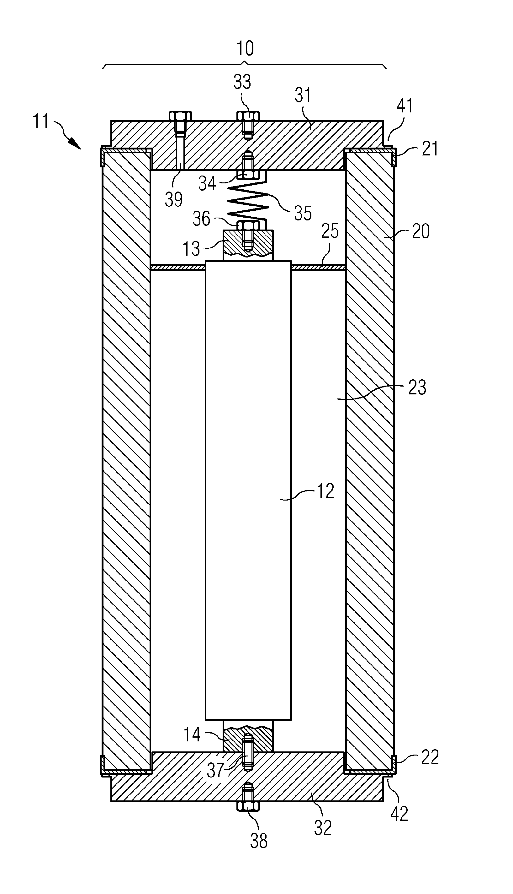
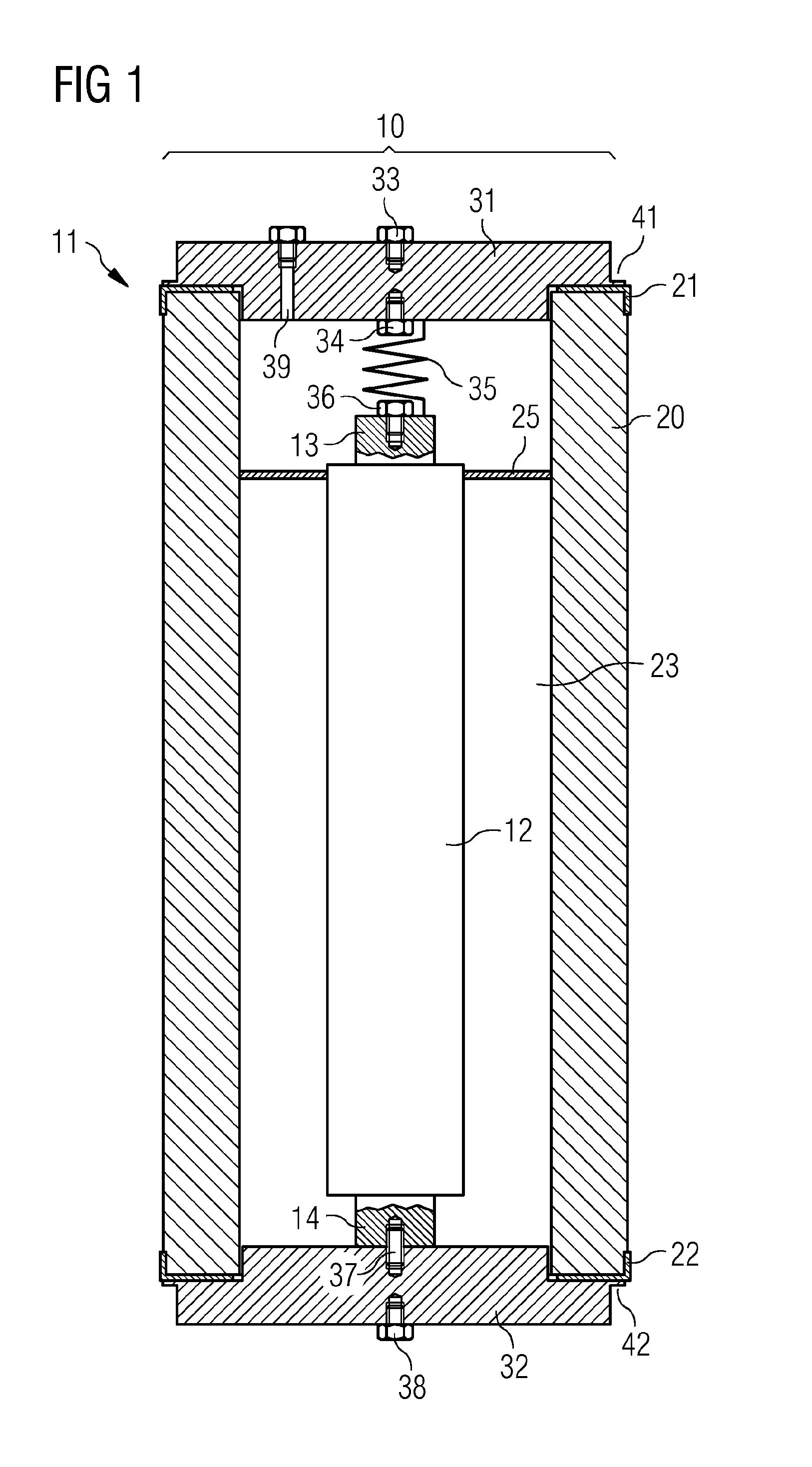
[0038]FIG. 1 shows schematically a subsea electric component 10 that includes a pressure resistant housing 11 and an electric component 12 arranged inside the pressure resistant housing 11. The subsea electric component 10 may be installed in a subsea application having a pressure compensated enclosure, such as a transformer, a switch gear, a subsea variable speed drive. Pressure compensated is used herein to indicate that the enclosure of the subsea application is filled with a dielectric liquid and is provided with a pressure (or volume) compensator, via which a pressure equalization between the external pressure of surrounding sea water and the int...


PUM


Abstract

A pressure resistant housing for an electric component is provided. The pressure resistant housing is adapted for the use in a subsea application. A ceramic housing body houses the electric component. The ceramic housing body has a first opening and a second opening that are closed by a first metal lid and a second metal lid, respectively.

Description

[0001]The present patent document is a §371 nationalization of PCT Application Serial Number PCT / EP2012 / 065173, filed Aug. 2, 2012, designating the United States, which is hereby incorporated by reference in its entirety. This patent document also claims the benefit of EP11179252.9, filed on Aug. 30, 2011, which is also hereby incorporated by reference in its entirety.BACKGROUND[0002]The present embodiments relate to a pressure resistant housing for an electric component, such as a fuse or a fuse element. The present embodiments further relate to a subsea electric component and a subsea fuse.[0003]Oil platforms are used in offshore oil and gas production. In the operation of offshore oil platforms, electronics may be installed under water, e.g., for controlling functions of a subsea Christmas tree or a subsea blow out preventer. More recently, processing facilities are being relocated to the ocean floor. Subsea installations may include processing equipment, such as electrically dri...

Claims


Application Information

Patent Timeline
IPC IPC(8): H05K5/00H02H9/04H01H85/175H05K5/02H01H85/17
CPCH05K5/0095H05K5/0004H02H9/04H01H85/17H01H85/175H05K5/0239H01H85/0013H01H85/165H01H85/042H05K5/03
Inventor BOE, OVE
Owner SIEMENS ENERGY AS
Why Eureka
Try Eureka