Uninterruptible power supply with a power isolation circuit loop

a power isolation circuit and loop technology, applied in emergency power supply arrangements, electrical equipment casings/cabinets/drawers, manufacturing tools, etc., can solve the problems of large circuit board size, complex circuits, and high ups cost, so as to reduce isolation parts and costs, simplify the isolation circuit, and save internal space utilization

Active Publication Date: 2014-12-25
CYBER POWER SYST
View PDF6 Cites 0 Cited by
  • Summary
  • Abstract
  • Description
  • Claims
  • Application Information

AI Technical Summary

Benefits of technology

[0007]An objective of the present invention is to provide a UPS with a power isolation circuit loop si

Problems solved by technology

However, additional isolated power source, optical coupler, isolated detection circuit, and the like are needed between a primary-side circuit and a secondary-side circuit, and the element cost and the challenge to

Method used


Image

  • Uninterruptible power supply with a power isolation circuit loop
  • Uninterruptible power supply with a power isolation circuit loop
  • Uninterruptible power supply with a power isolation circuit loop

Examples


first embodiment

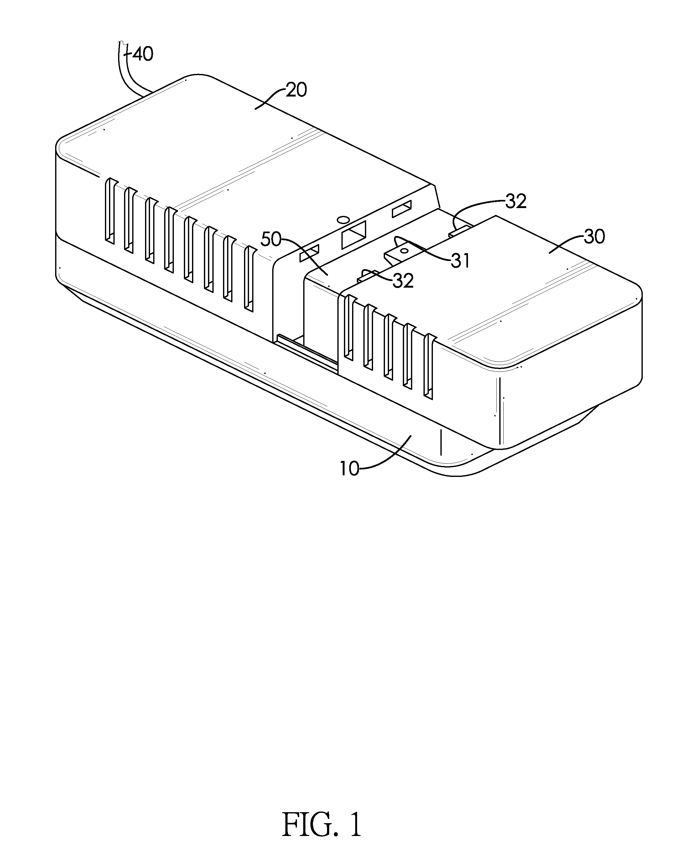
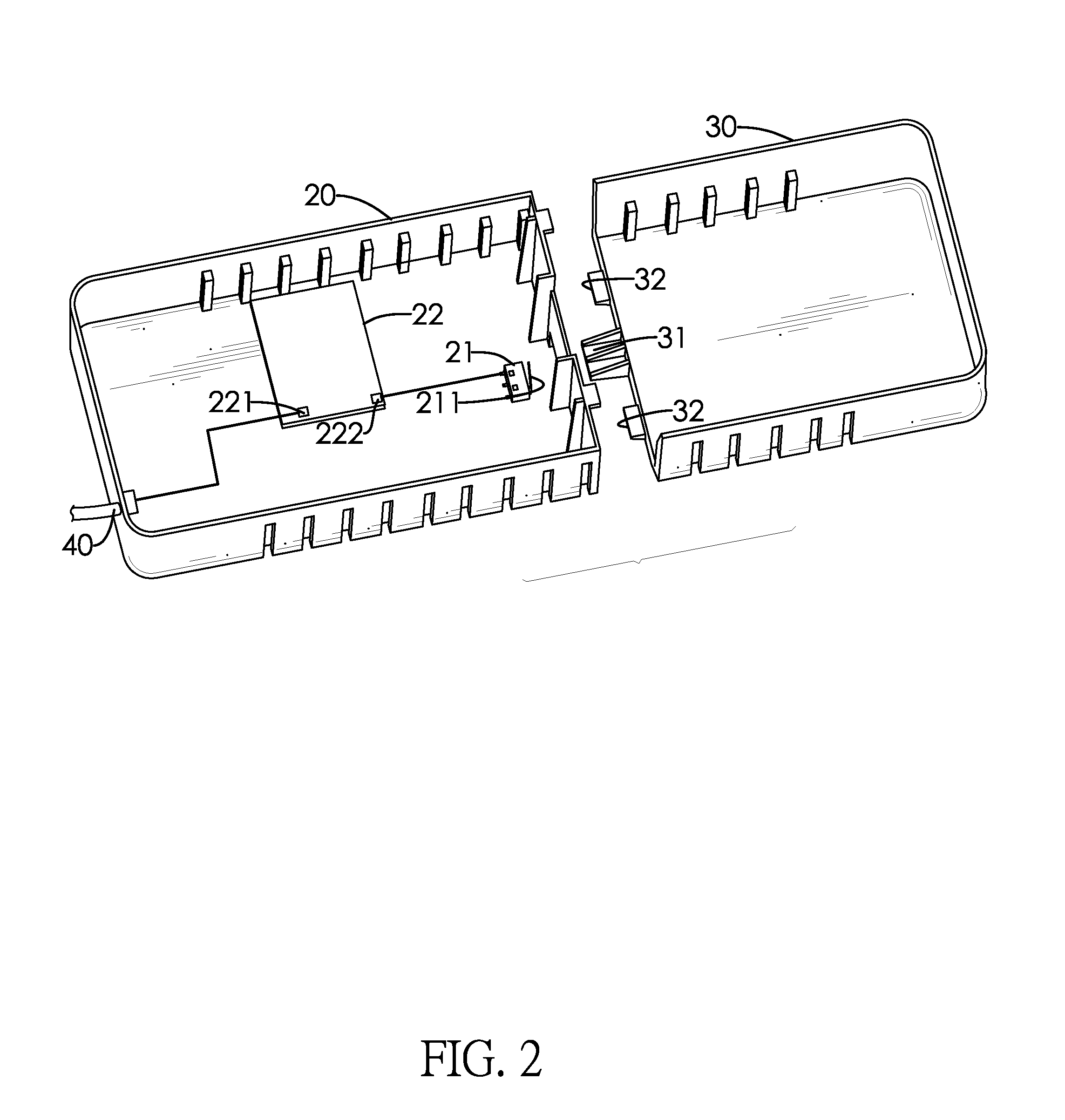
[0028]With reference to FIG. 3, an isolated protection circuit of the UPS has a power control circuit 60 formed on the circuit board 22 and connected to a power source. The loop switch 21 is connected between the power control circuit 60 and a circuit loop BAT-V inside the battery chamber. The power control circuit 60 has an electronic switch Q1 and a voltage regulator U1. The voltage regulator U1 has a voltage input terminal and a voltage output terminal. The electronic switch Q1 has an input terminal and an output terminal. The input terminal is connected to the loop switch 21. The output terminal is connected to the voltage input terminal of the voltage regulator U1. The electronic switch Q1 acquires a 12V DC power from the loop switch 21, and supplies the 12V DC power through the output terminal of the electronic switch Q1. The voltage regulator U regulates the 12V DC power and supplies a 5V DC power through the voltage output terminal thereof. Thus, DC power with different volt...

second embodiment

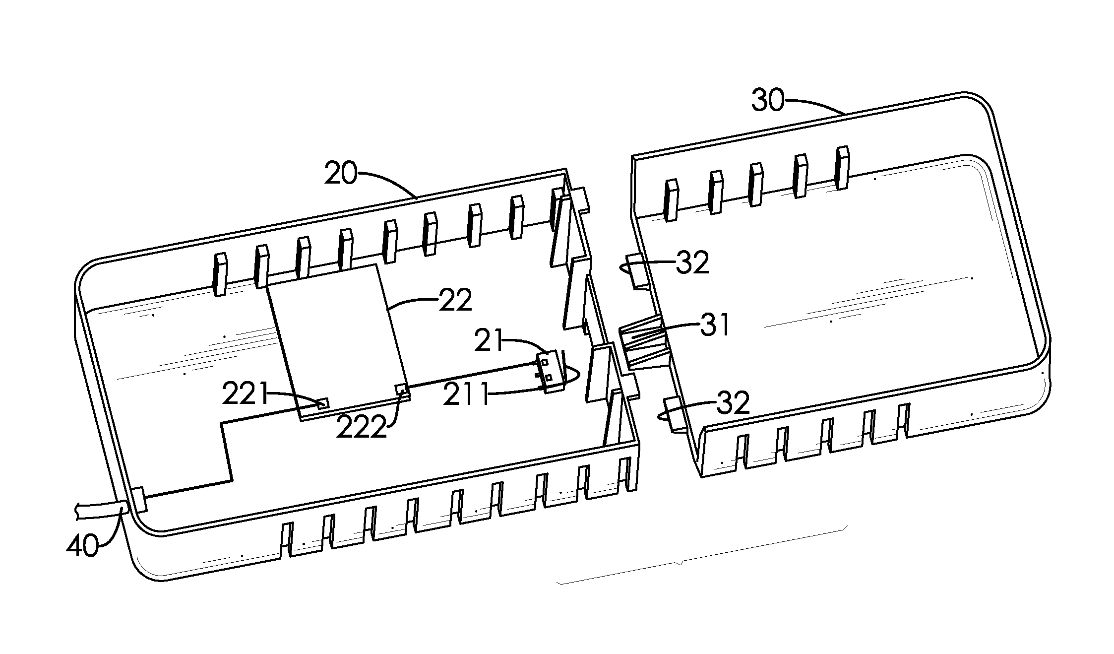
[0029]With reference to FIGS. 4 and 5, an isolated protection circuit of the UPS has a microcontroller unit (MCU) 23, a relay 24 and a switching circuit 25. The switching circuit 25 has a control terminal and an input terminal. The relay 24 is formed by a normally closed switch and an excitation coil. The excitation coil is connected between a 12V input power source and the input terminal of the switching circuit 25 for controlling a switching state of the normally closed switch. The MCU 23 has multiple pins. One of the pins D-SWITCH is electronically connected to the loop switch 21. Another pin INPUT-RLY is electronically connected to the control terminal of the switching circuit 25. The loop switch 21 is connected to a 5V DC power source. When the movable top cover 30 is mounted on the base 10, the loop switch 21 is switched on to provide a 5V voltage to a pin D-SWITCH of the MCU 23. Under this circumstance, a pin INPUT-RLY of the MCU 23 does not output a signal to drive the switc...


PUM

PropertyMeasurementUnit
Poweraaaaaaaaaa

Abstract

An interruptible power supply with a power isolation circuit loop has a base with a battery chamber defined in the base, a fixed top cover, and a movable top cover. The battery chamber serves to receive a battery. The fixed top cover and the movable top cover are mounted on two ends of the base, and the movable top cover corresponds to the battery chamber. The fixed top cover has a loop switch therein connected with a power loop and having an actuation member to switch on or off the power loop. When the movable top cover is mounted on the base, an urging member formed on the movable top cover triggers the actuation member of the loop switch to connect with the power loop. When the movable top cover is removed, the power loop is disconnected. Accordingly, the UPS is economical in terms of parts, cost and space utilization.

Description

BACKGROUND OF THE INVENTION[0001]1. Field of the Invention[0002]The present invention relates to an uninterruptible power supply (UPS), and more particularly to a UPS with a power isolation circuit loop.[0003]2. Description of the Related Art[0004]Conventional UPSs in the market are connected to electric / electronic appliances and mainly serve to supply power during power outage. Certain UPSs also provide functions for irregular power prevention and noise immunity to protect electric / electronic equipment, especially for precision instruments requiring higher power quality. By and large, UPS is not major equipment to users unless users have a demand for higher power quality.[0005]Taiwan Power Company announces that the average power outage time per power consumer in the science parks island-wide is 1.2 minute (about 72 seconds) in 2010. Such power supply performance can be ranked high in terms of power supply quality because those power consumers in the science parks are densely conce...

Claims


Application Information

Patent Timeline
IPC IPC(8): H02J9/06H05K7/02
CPCH05K7/02H02J9/061H05K7/1432
Inventor WANG, JIAN
Owner CYBER POWER SYST
Why Eureka
Try Eureka